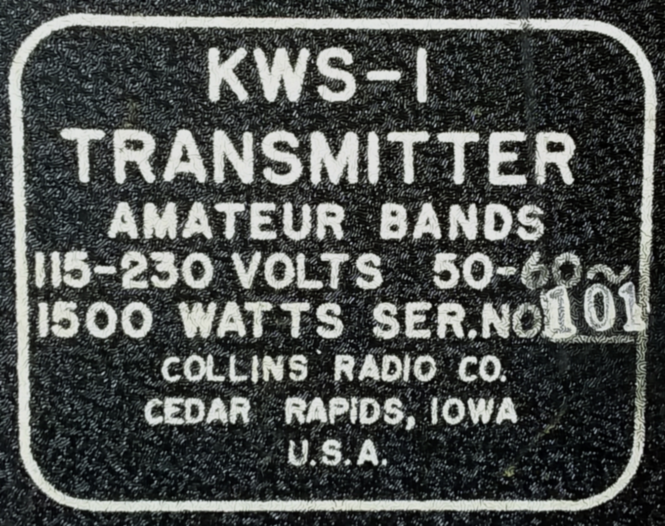
| KWS-1 #101: A Rehab |
|---|
|
| The Rehab | |
|---|---|
|
First Inspection So all I know about this KWS-1 is that it powers up and there's no grid drive to the finals. |
|
|
|
|
The first thing I noticed when I opened it up and started inspecting it was a cracked bumble bee capacitor, C303 in the driver tube area. Perhaps a clue to the missing grid drive. |
|
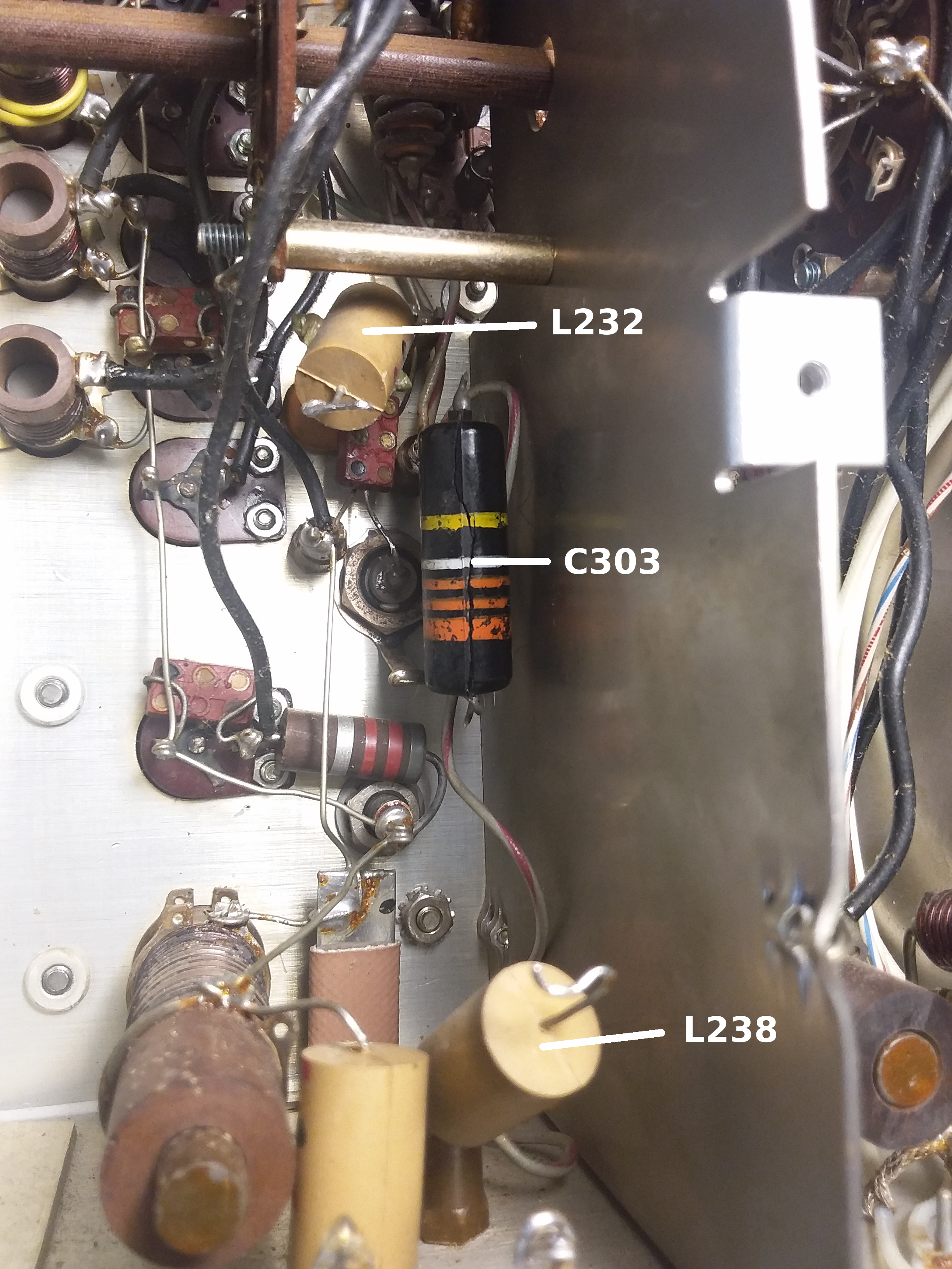
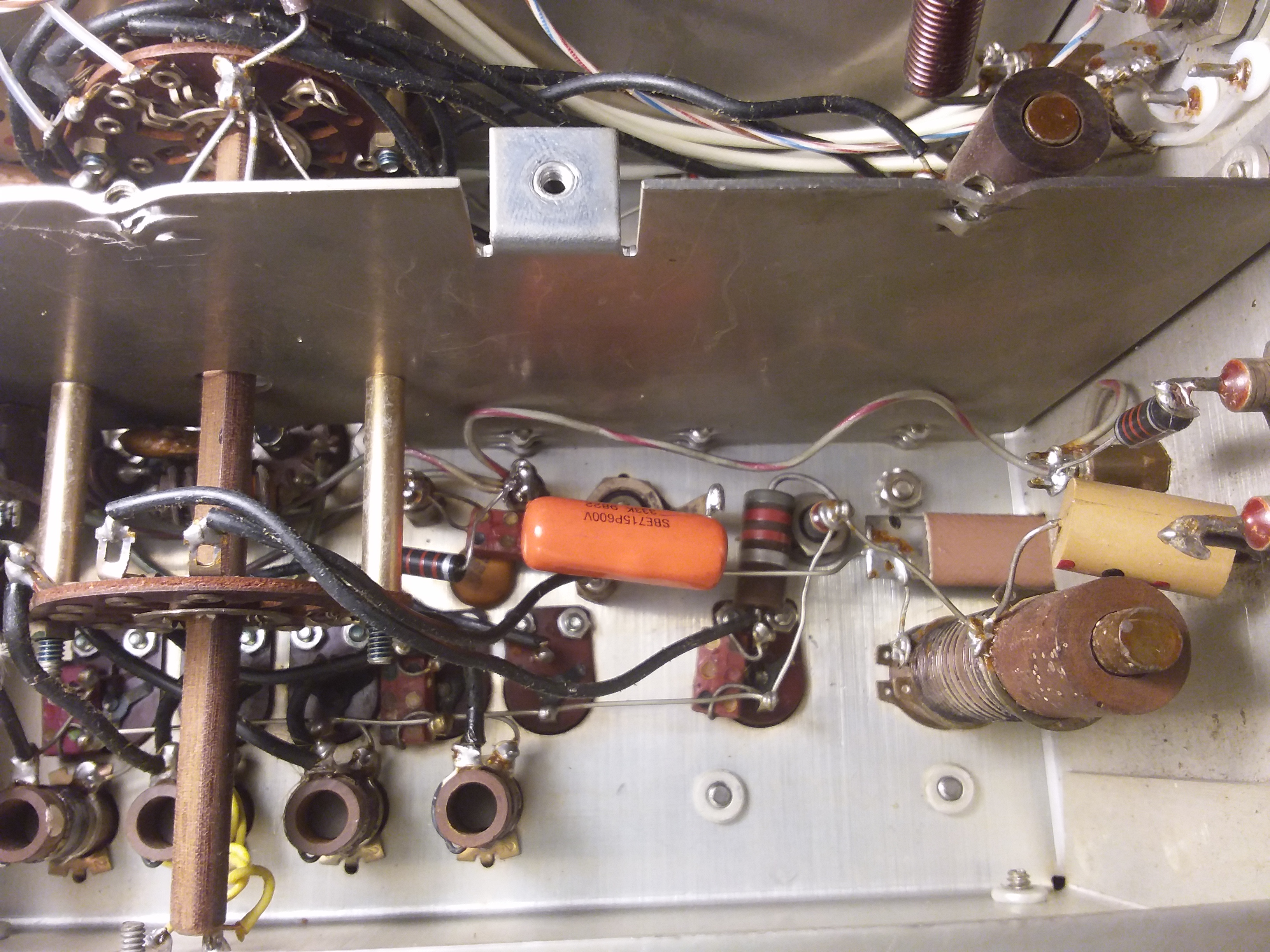 C303 cracked open and the fix |
|
|
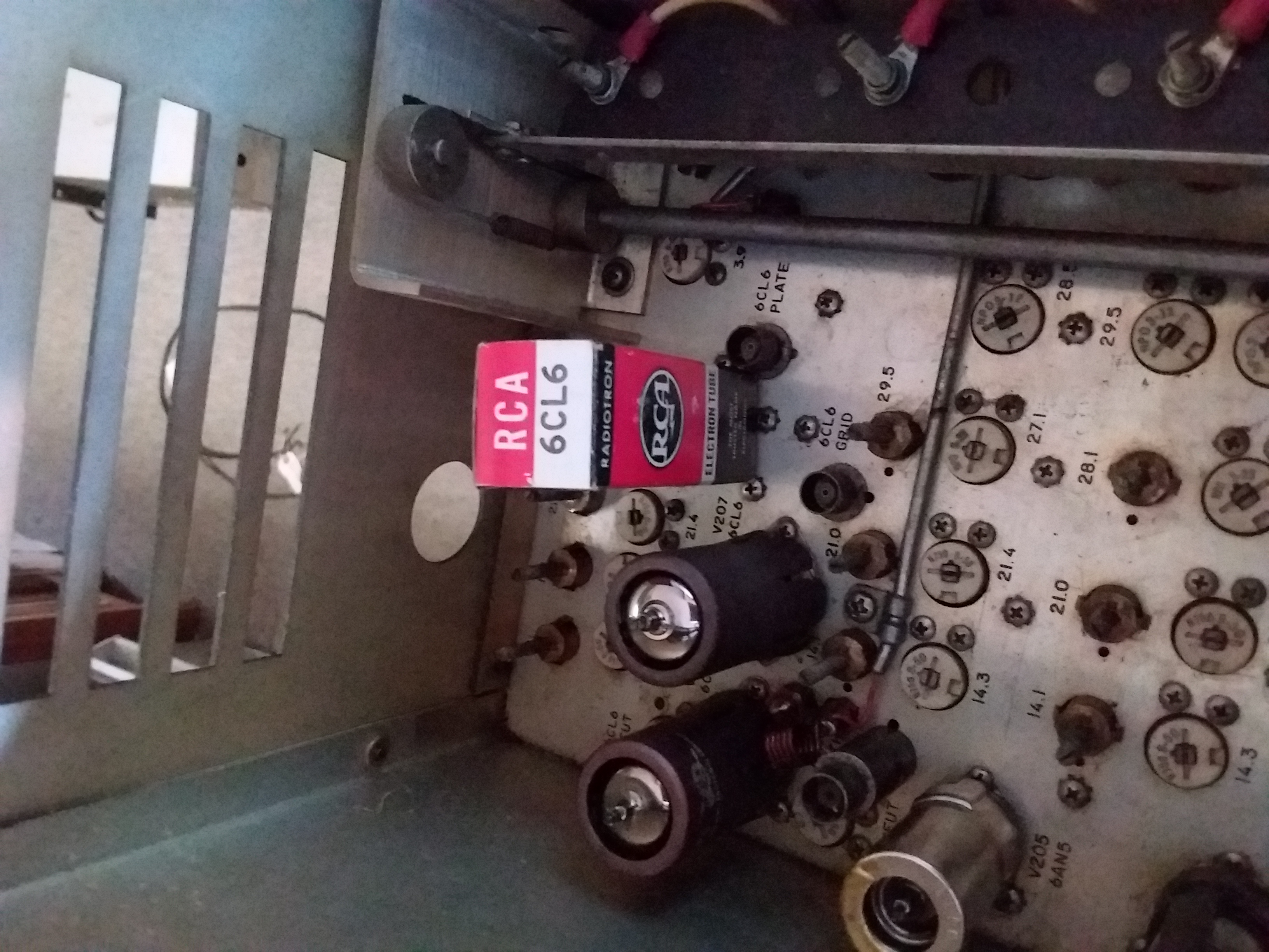
C303 is in the +275V B+ line so I traced it back and found that RF choke L238 had also opened up. So there was the missing B+ to the 2 6CL6 drivers. I noticed that L232, directly to the left of the cracked capacitor had 2 strange greenish ears sticking out of the molded seam on each side of the inductor. I measured it and it was 0mH. My guess is that the bumble bee shorted out and took L238 with it. But before it cracked open it was heating up and cooking L232 right next to it which caused it to bubble out at the seams. |
|
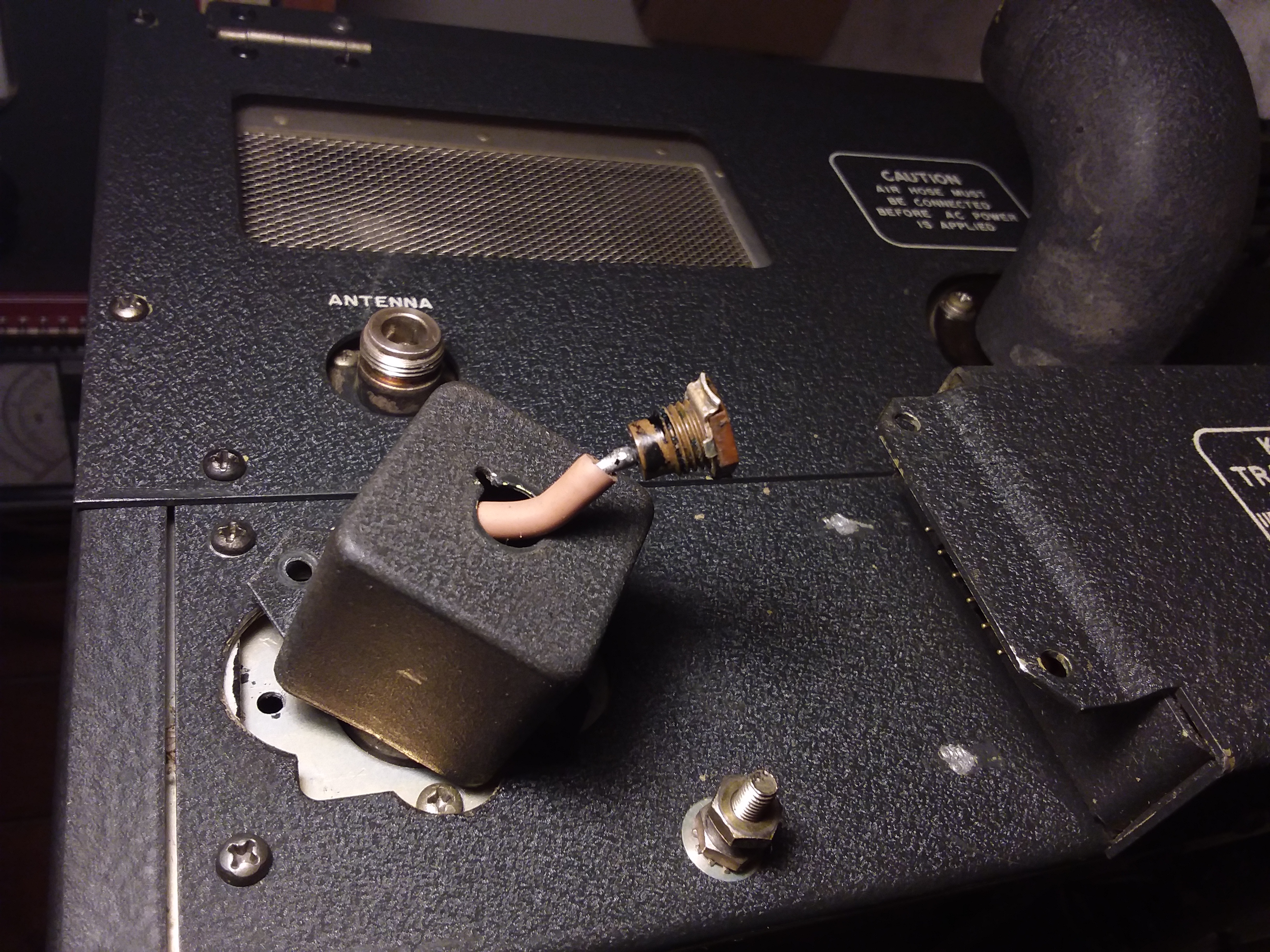
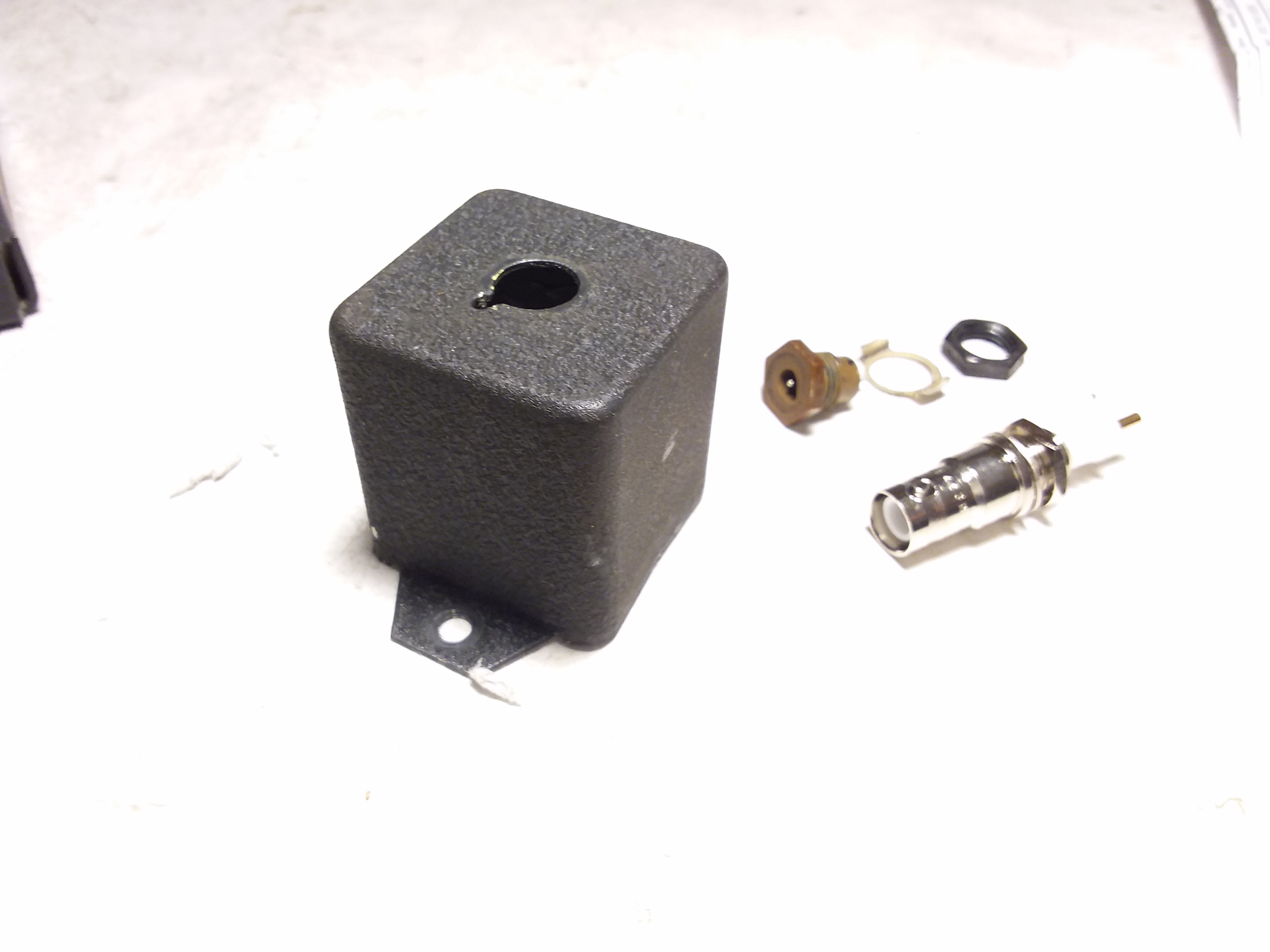
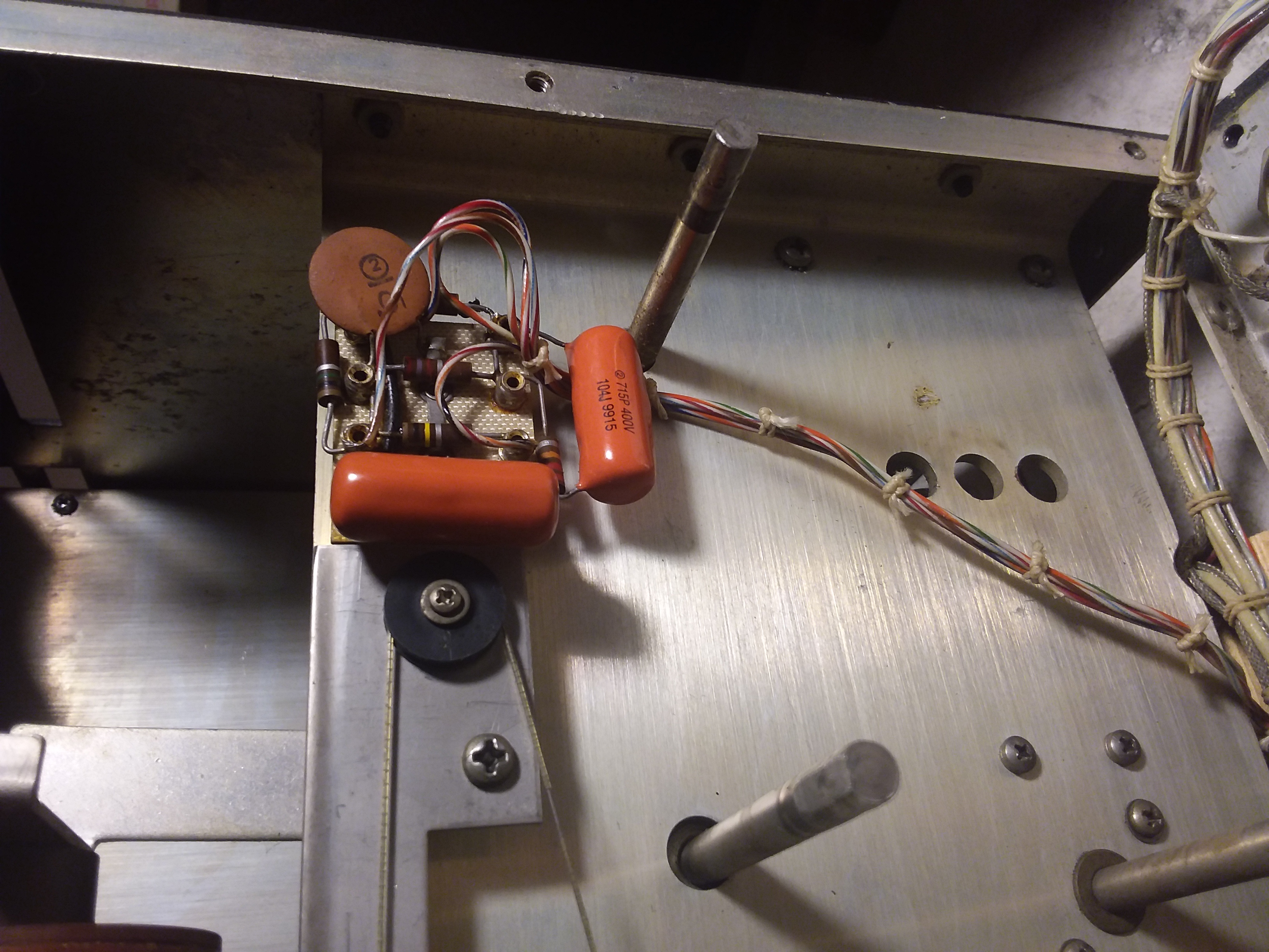
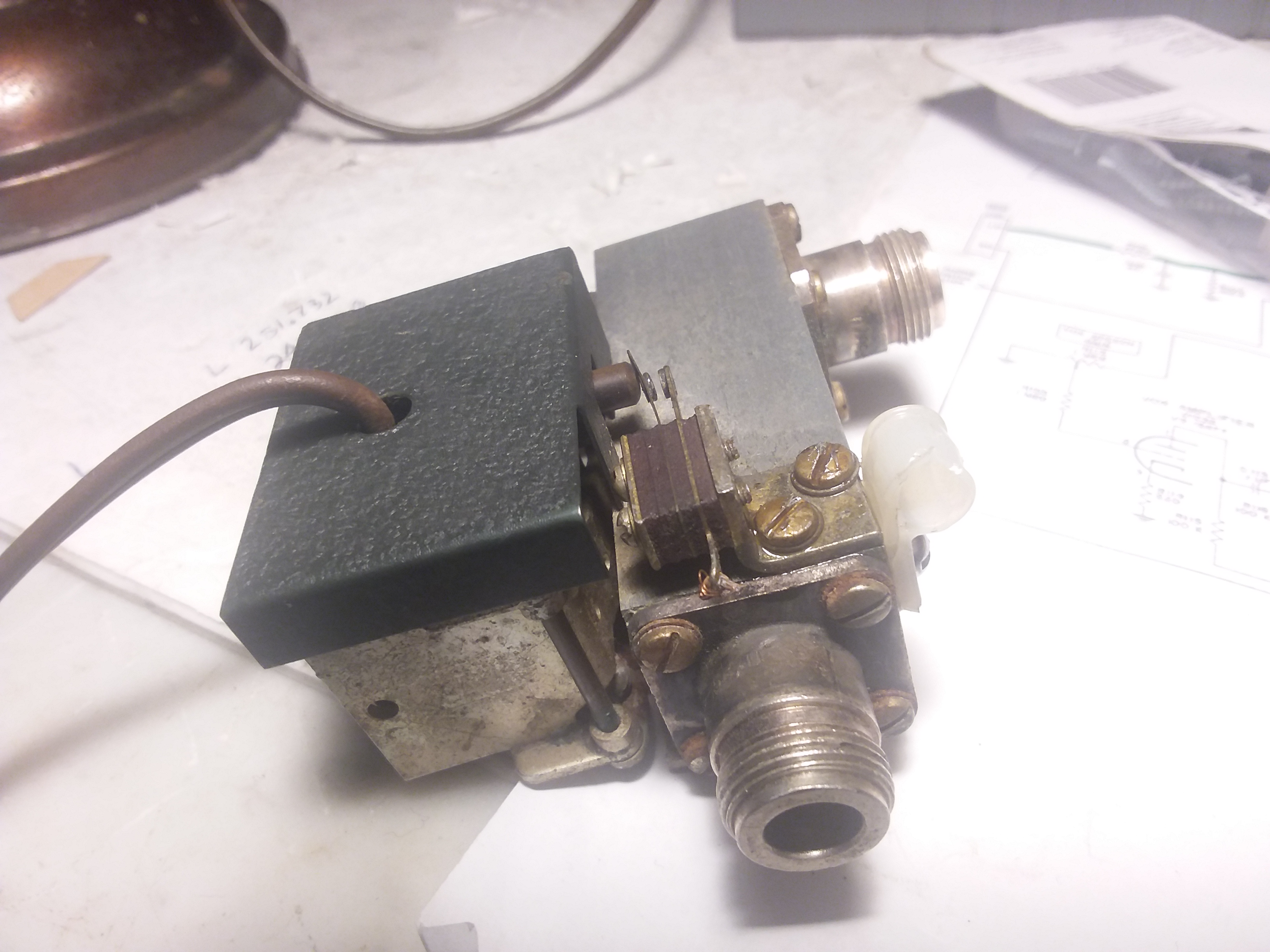
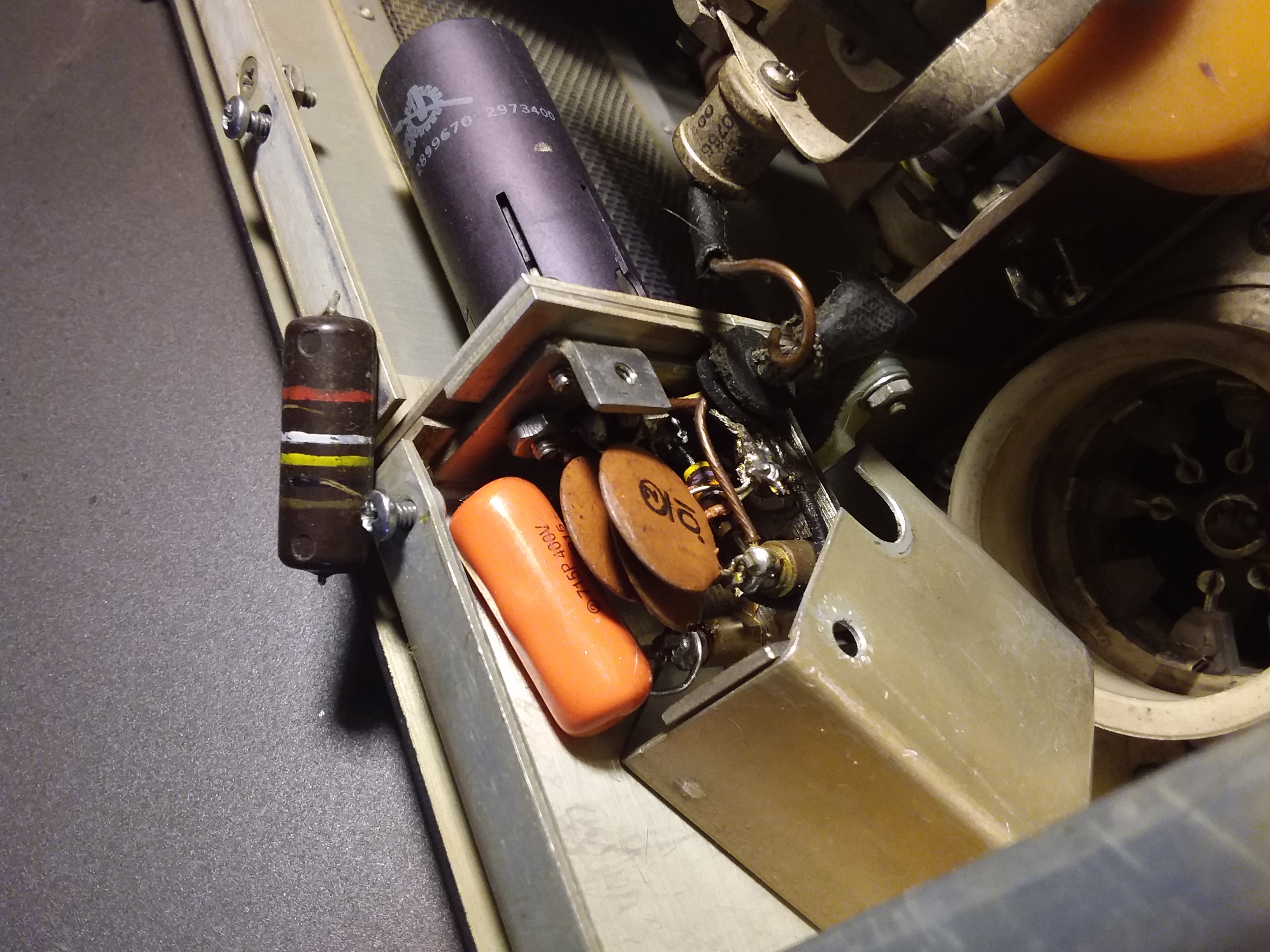 ALC capacitor C413 |
|
|
I found a copy of WA4HHG Chuck Rippel's KWS-1 "caps that must go" list and started hunting around for other likely replacements. Inside the ALC box in the PA section was C413 another bumble bee to get replaced. Down in the audio section I replaced the 3 yellow CDE caps with newer ones because they were easy to get at. |
|
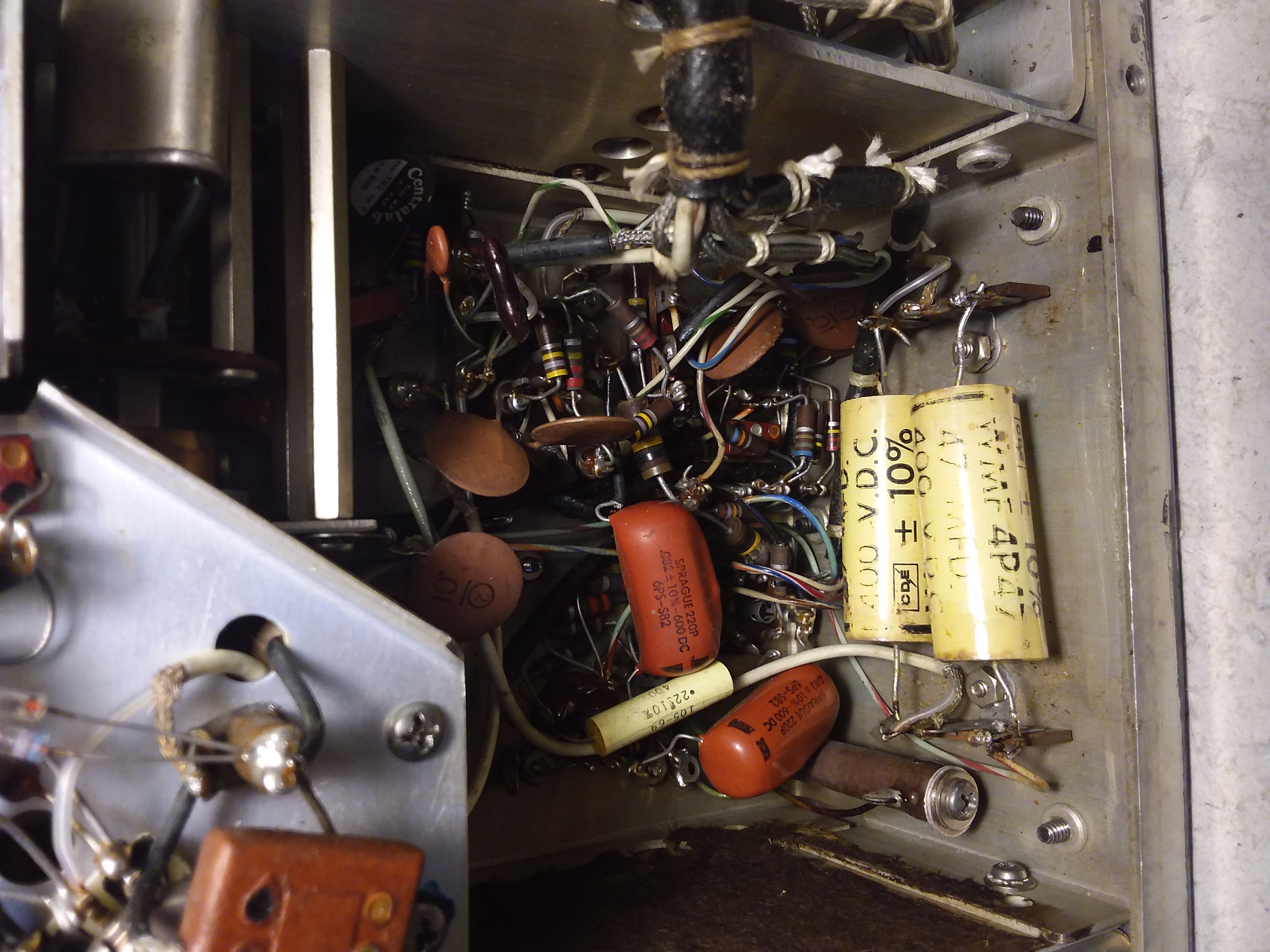
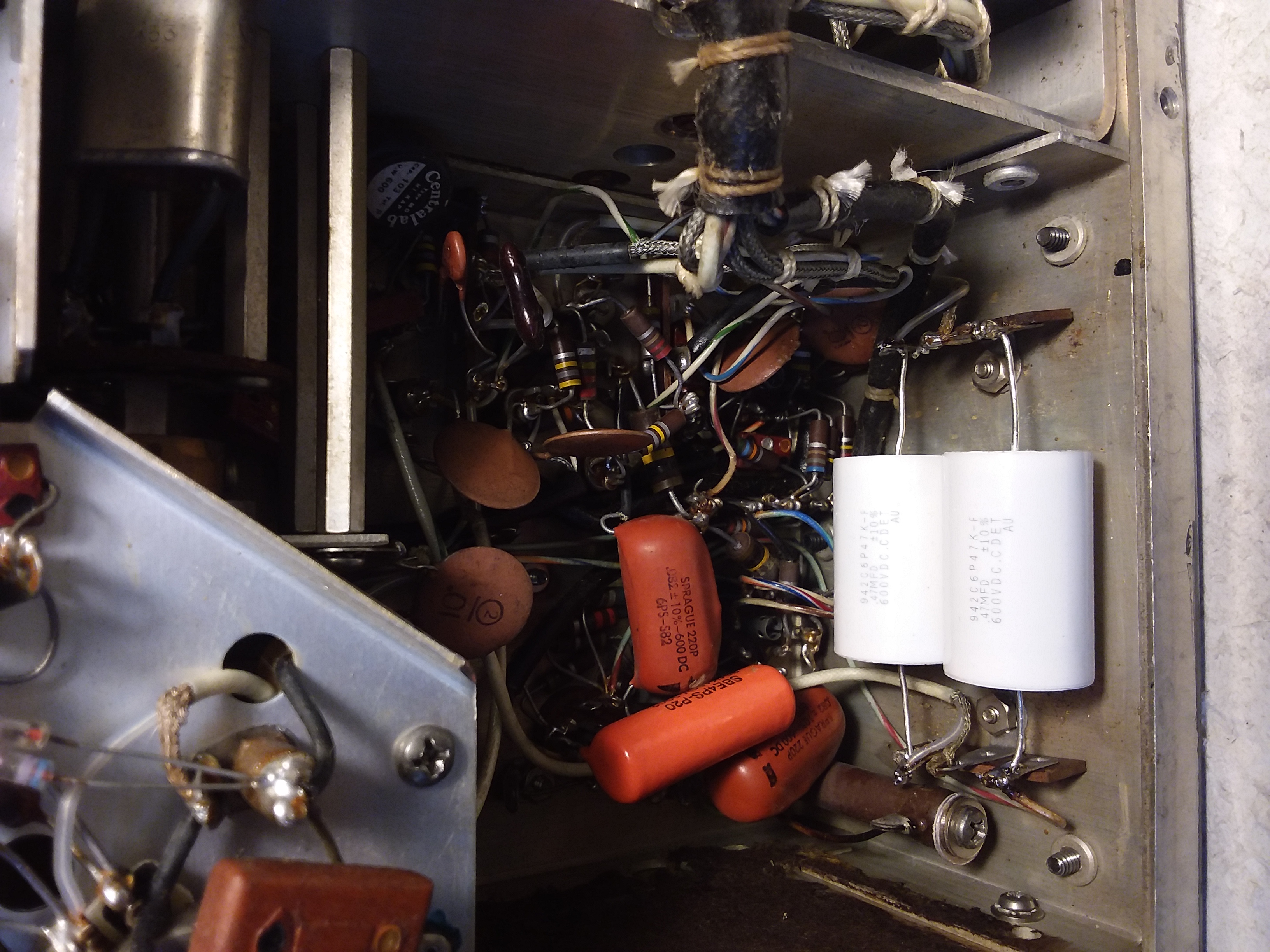 Audio capacitors old and new |
|
|
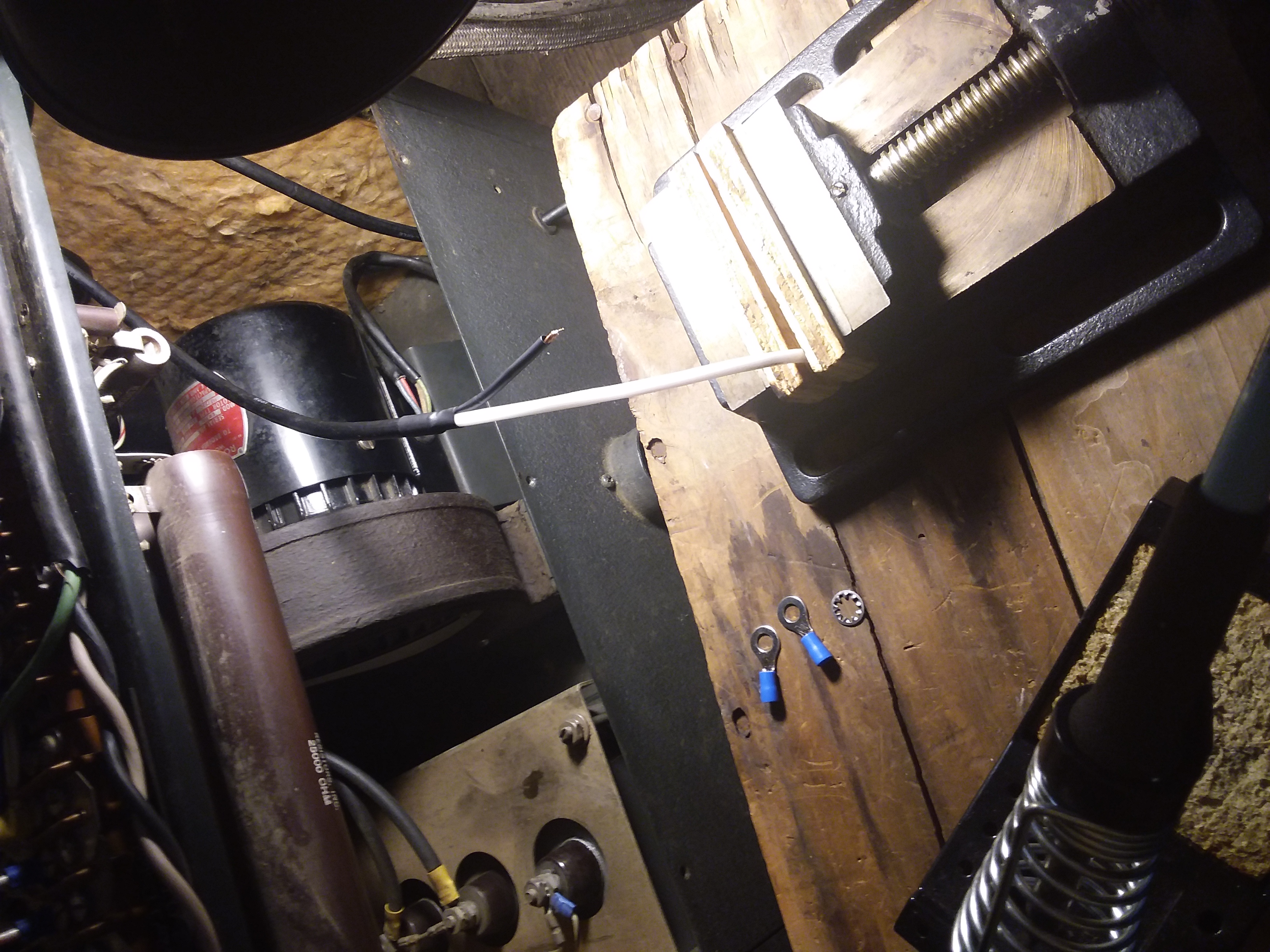
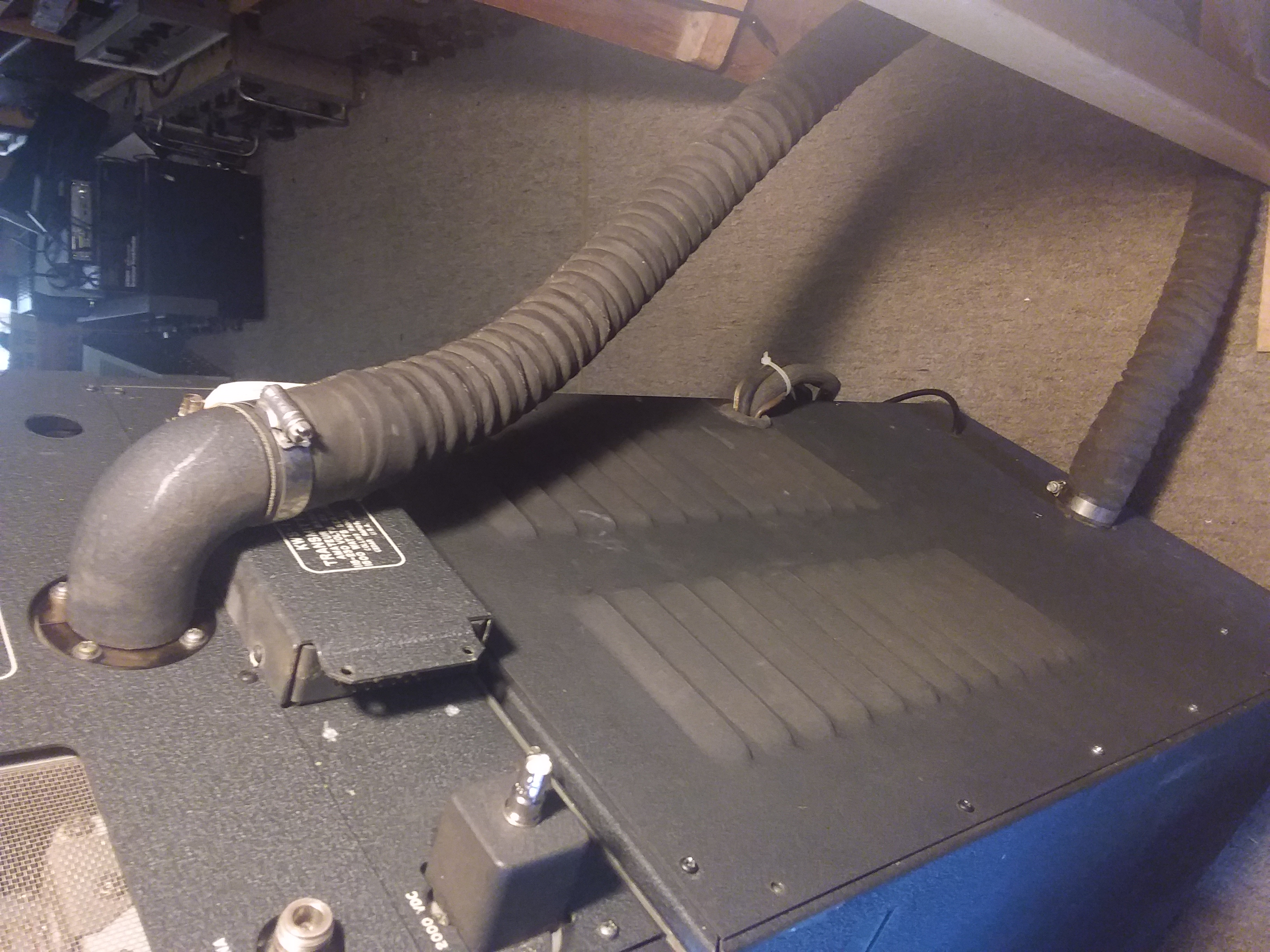
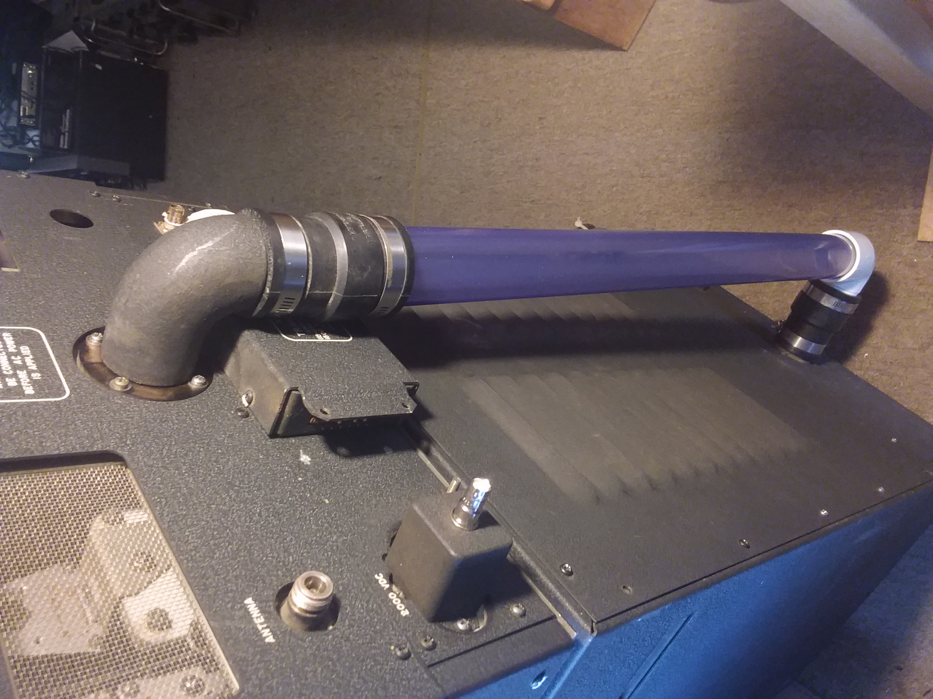
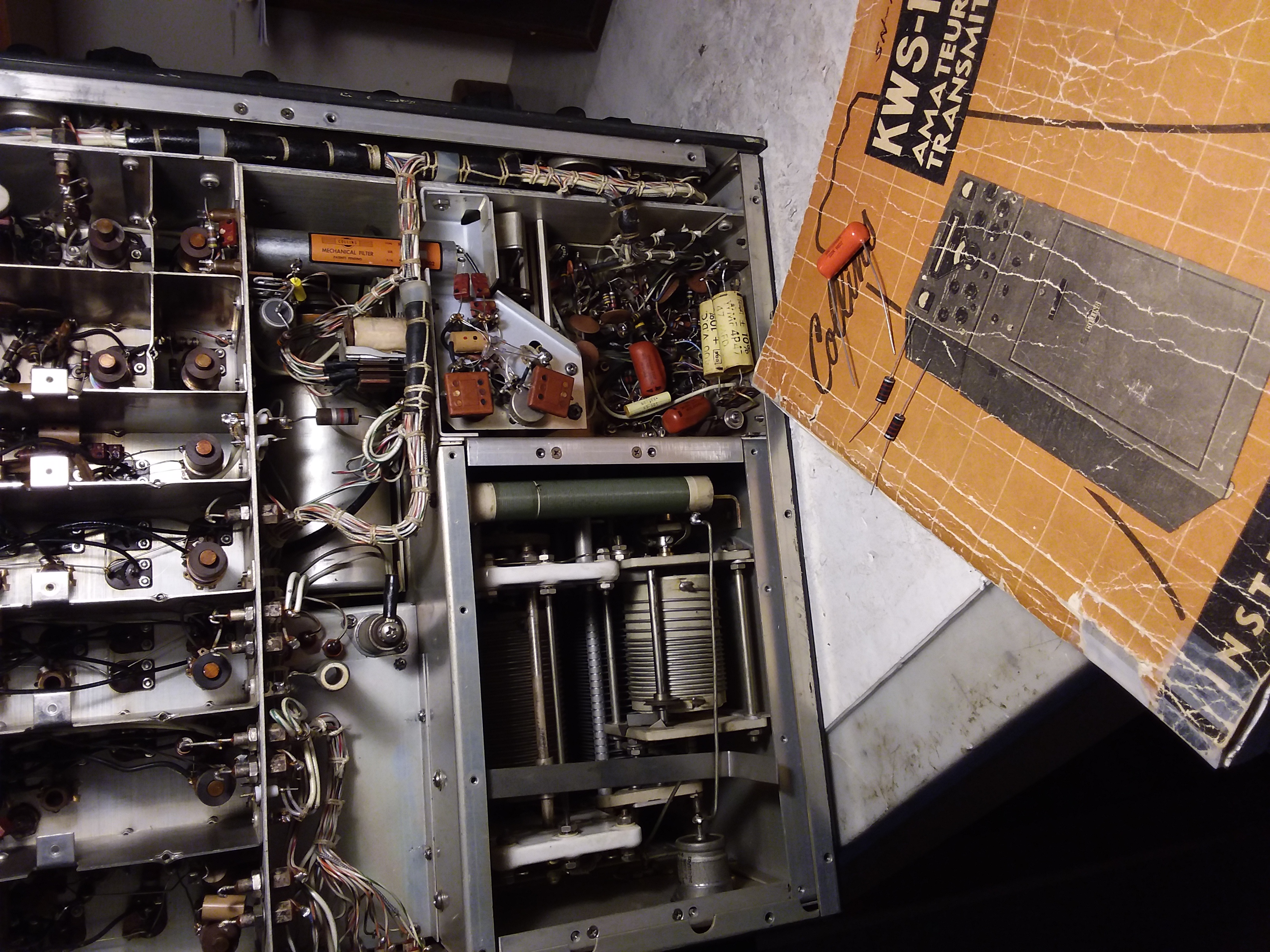
Other than a solder splice in the Plate Choke which may or may not be a problem I didn't notice anymore obvious problems underneath so I buttoned it up and started on replacing the HV line. |
|
 A splice in the Plate Choke |
|
|
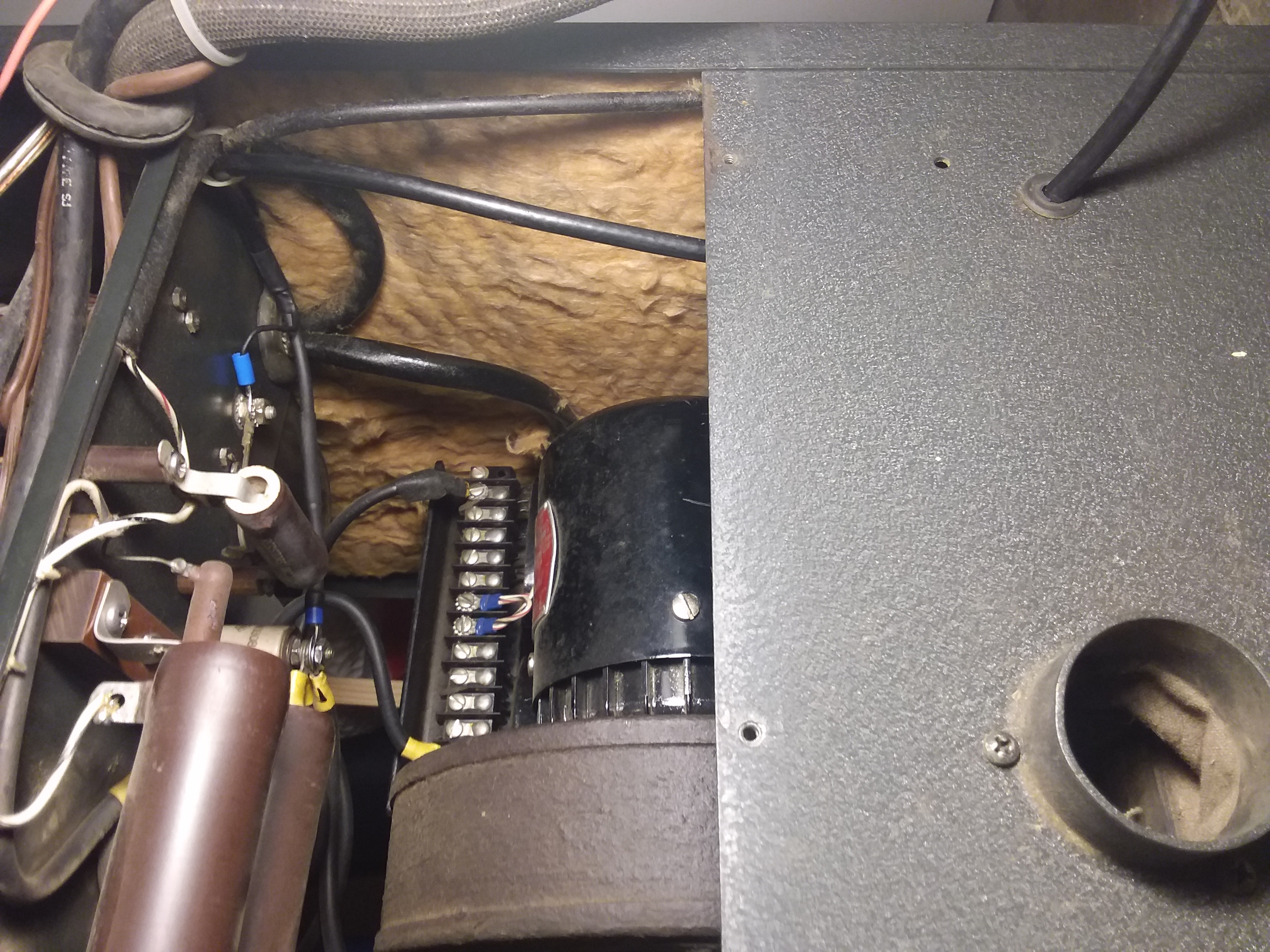
Insulating L105 While I was rooting around down in the power supply cabinet I added some insulation to the mounting bolts on L105 the HV filter choke. The Spring 1992 issue of The Collins Collector's Quarterly Magazine is entitled "KWS-1 The care and feeding, and other trivia" by N7OTQ Bill Carns. He points out that L105 has a high failure rate due to the proximity of the high voltage windings to the metal bolts. He suggests covering the bolts with 3/16 inch heat shrink tubing which I did. |
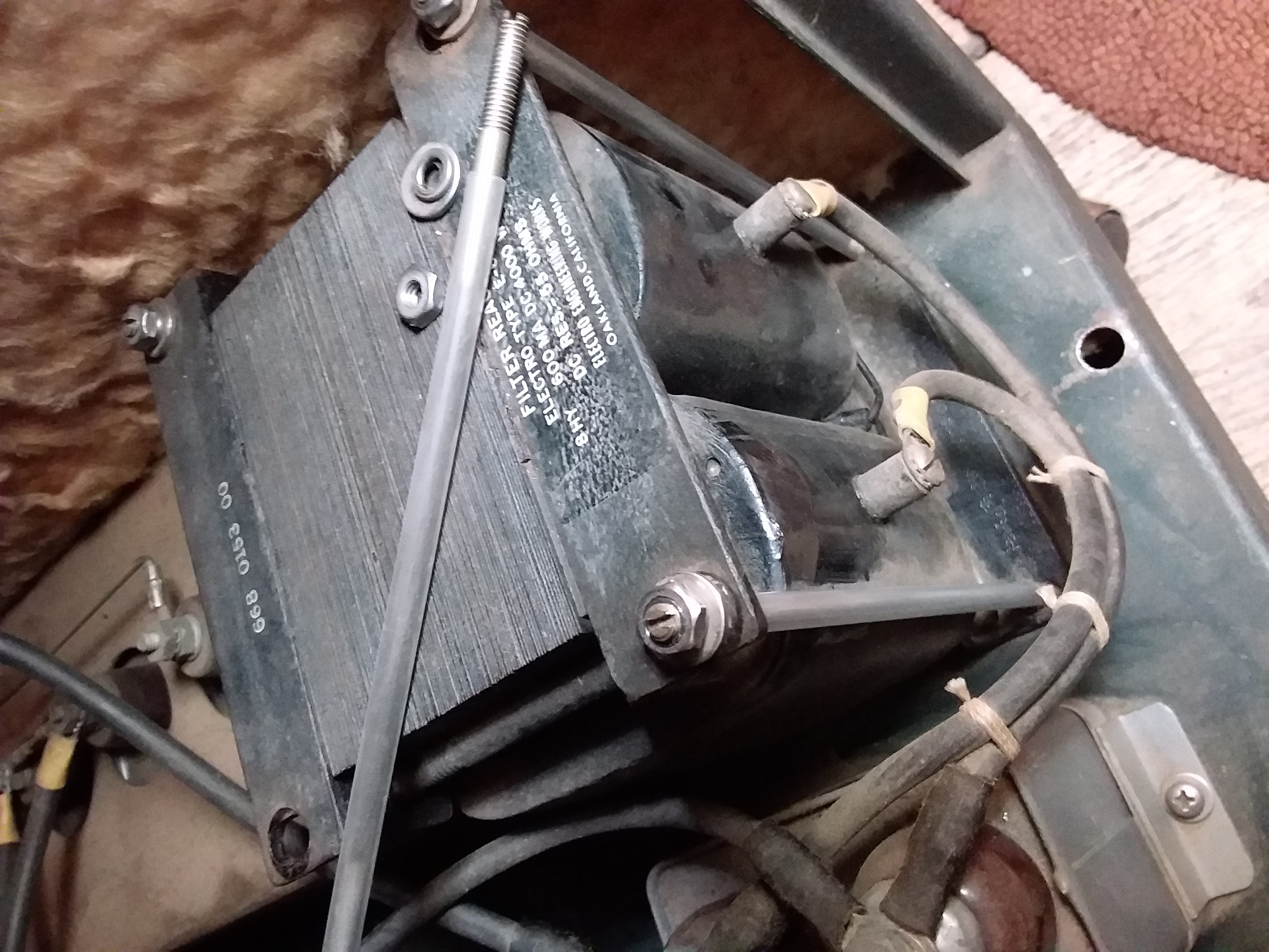
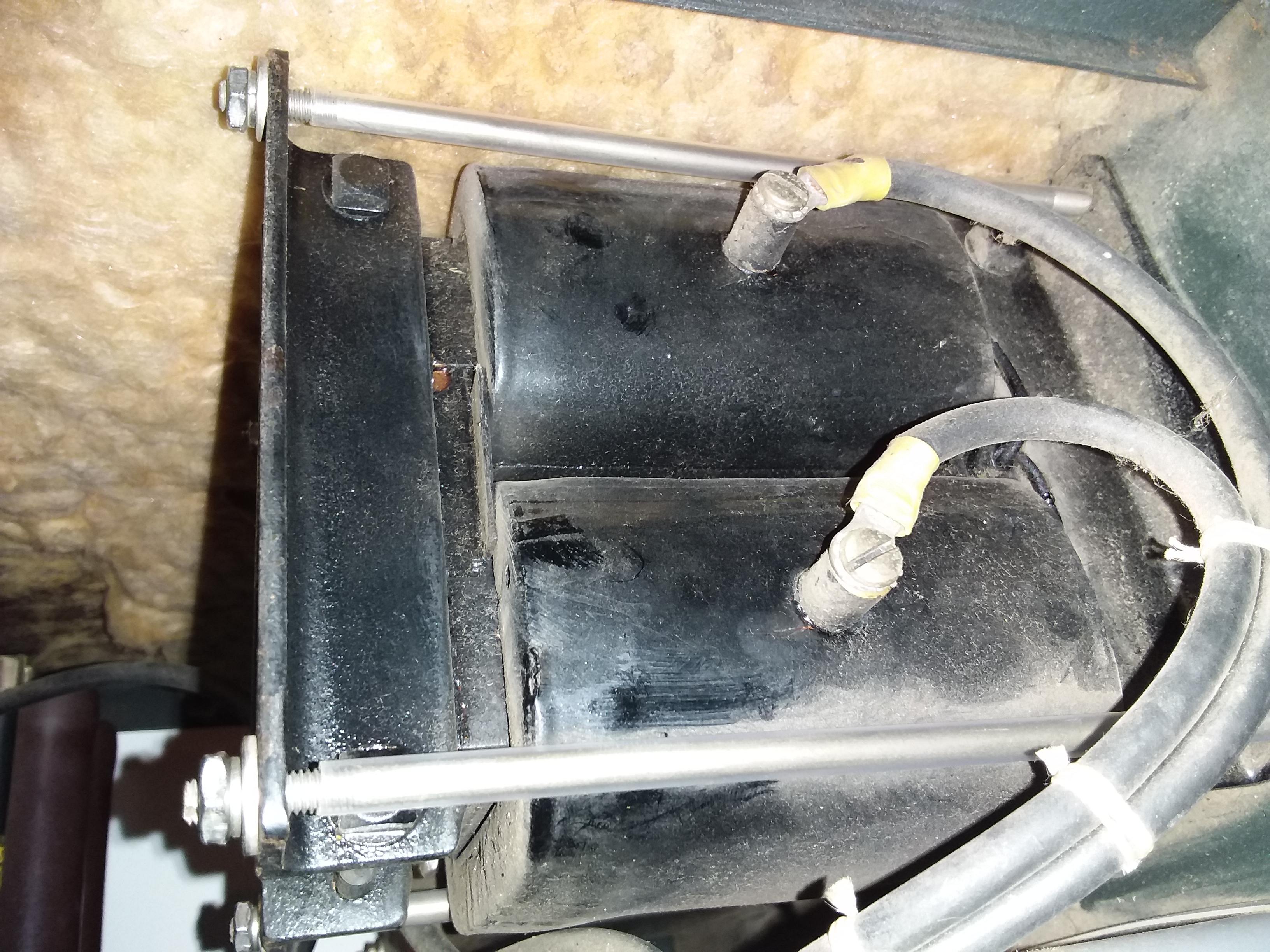 Insulation on the HV Filter Choke |
|
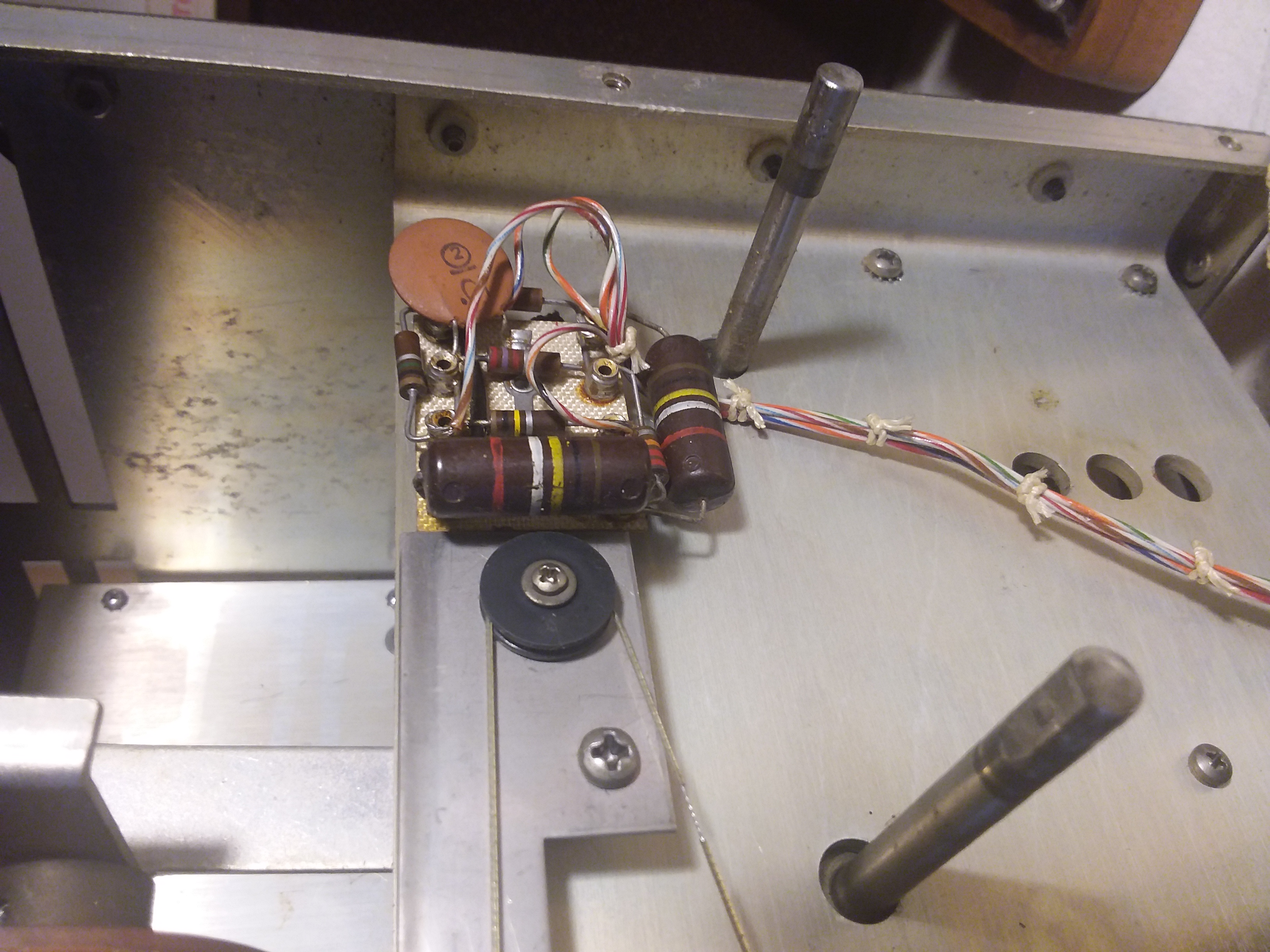
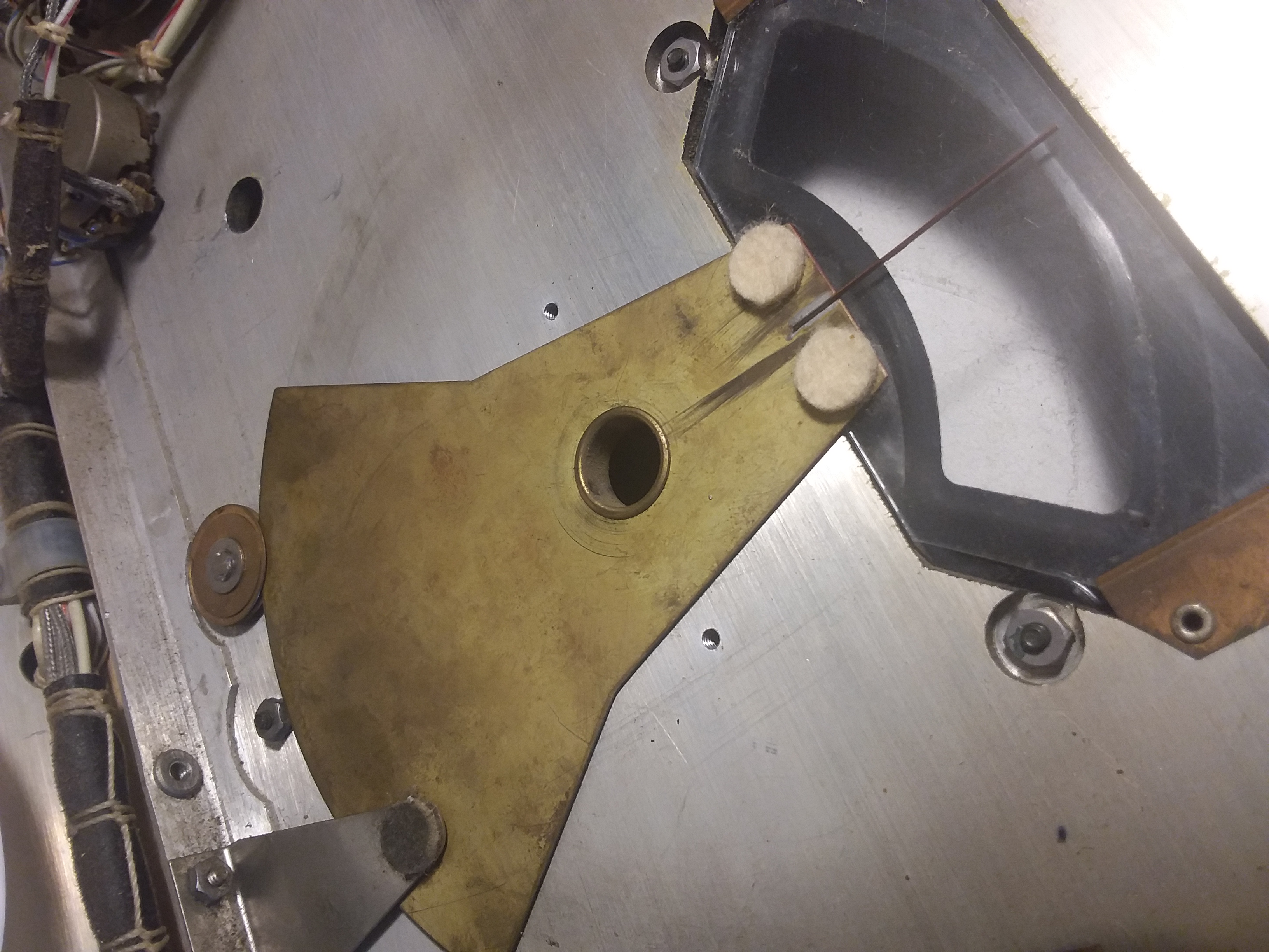
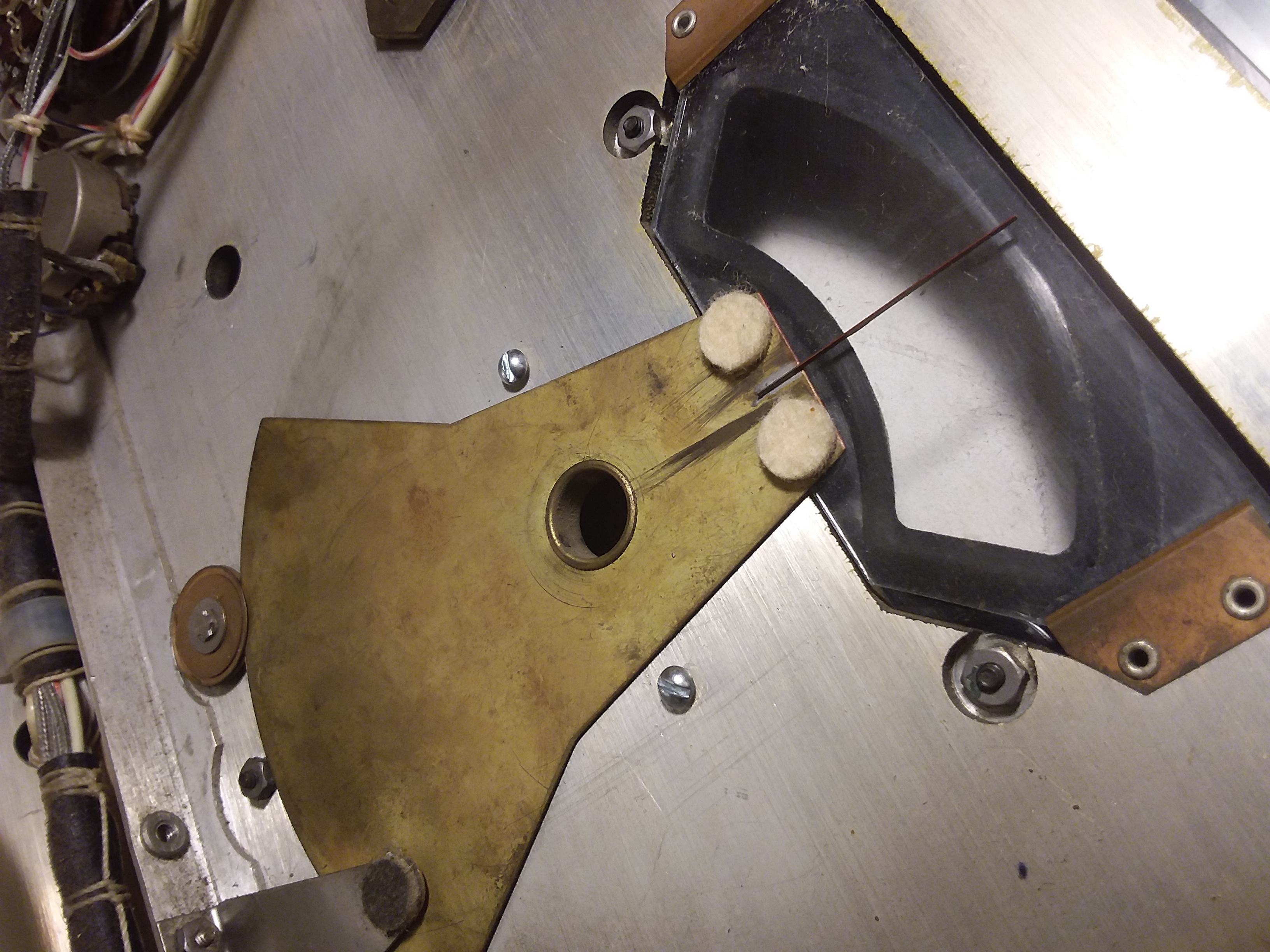
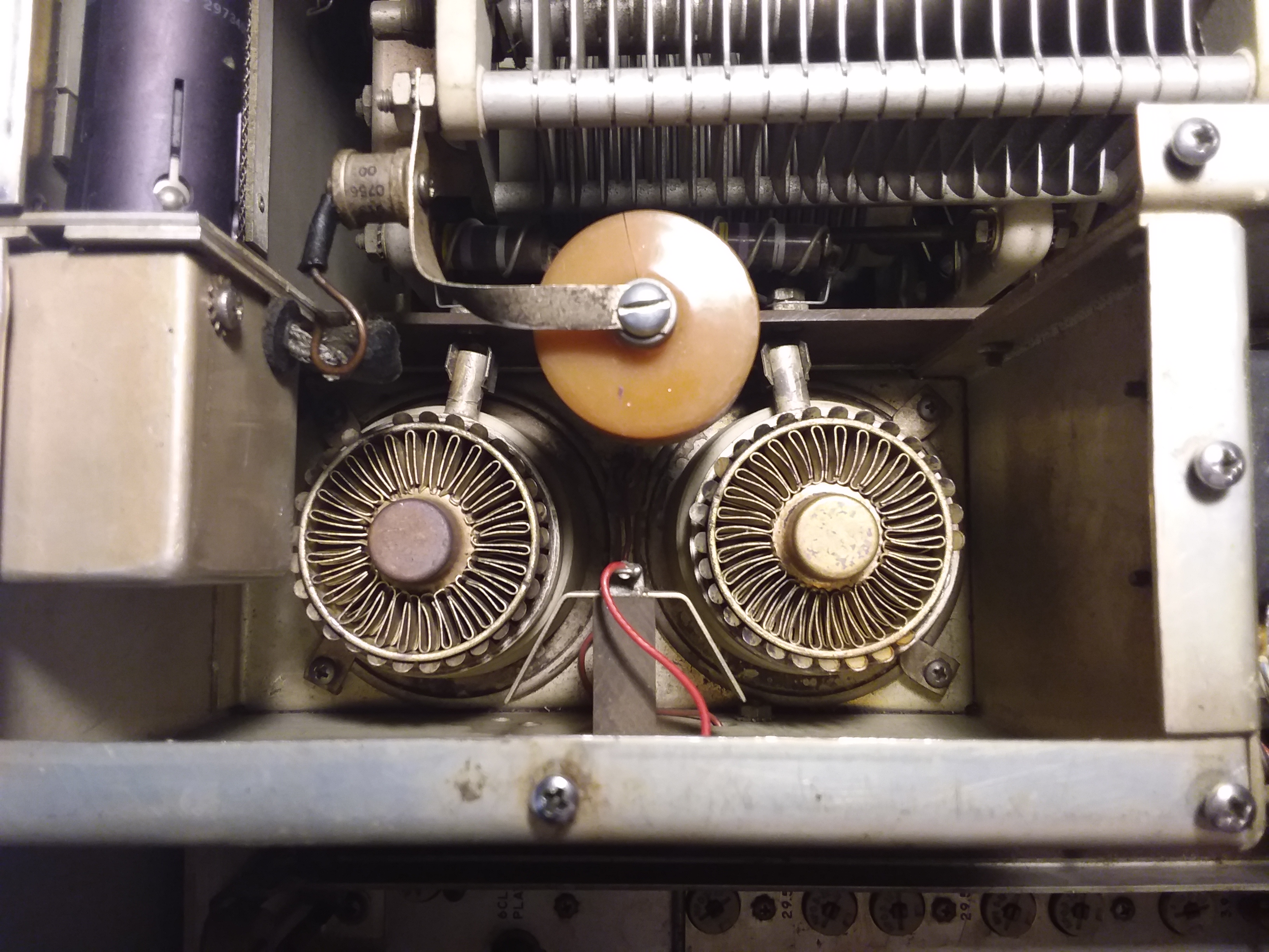
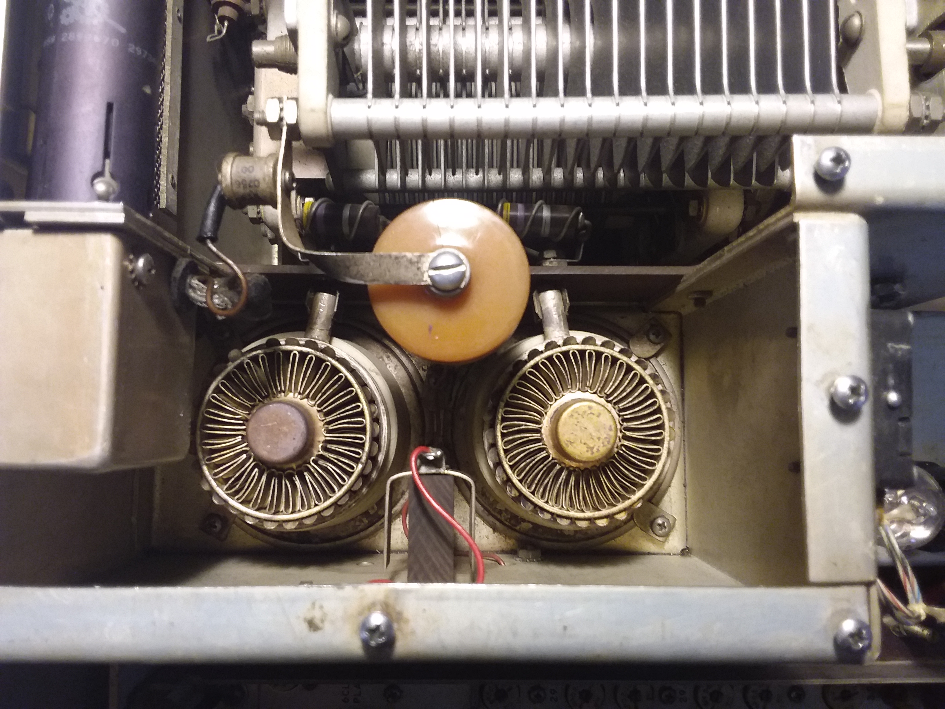
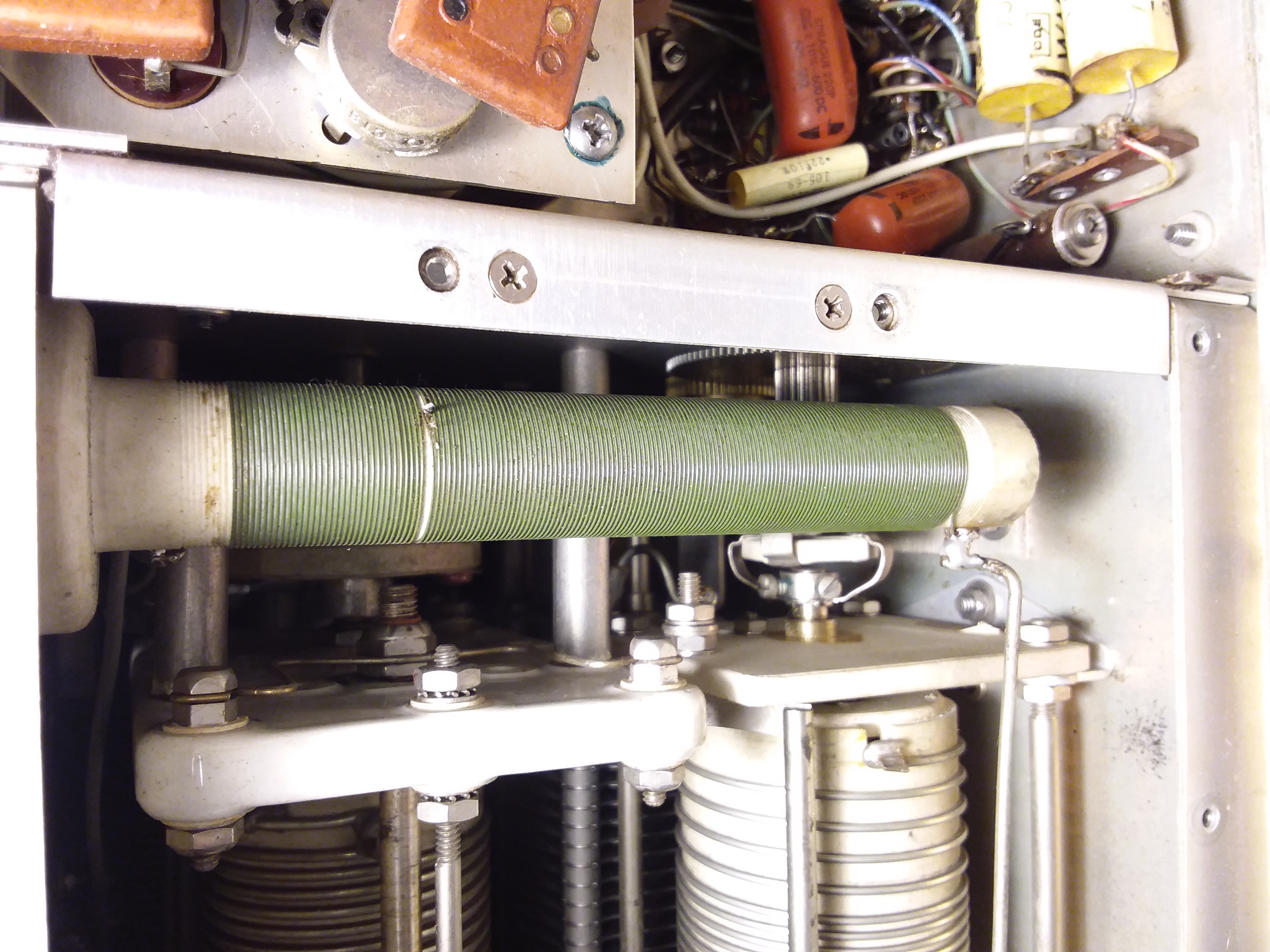
Tuning And Loading Synchronization Now to check the tuning synchronization. I reinstalled the front panel and reset the Tune and Load dials down to 0-0. I flipped the rig over to get a look at the PA cage from the bottom. The Tune inductor roller was sitting at the very end of the coil, right up against the solder blob stop. The Load roller was sitting 1 turn from the end. They needed adjusting. The Tuning capacitor was fully closed but the Loading dual capacitor was halfway in and out. It needed adjusting. I reset the Loading dial until the capacitors were fully meshed. Then I moved both inductor rollers until they were in their proper positions. I pulled both knobs, reset them to 0-0 and reinstalled them. |
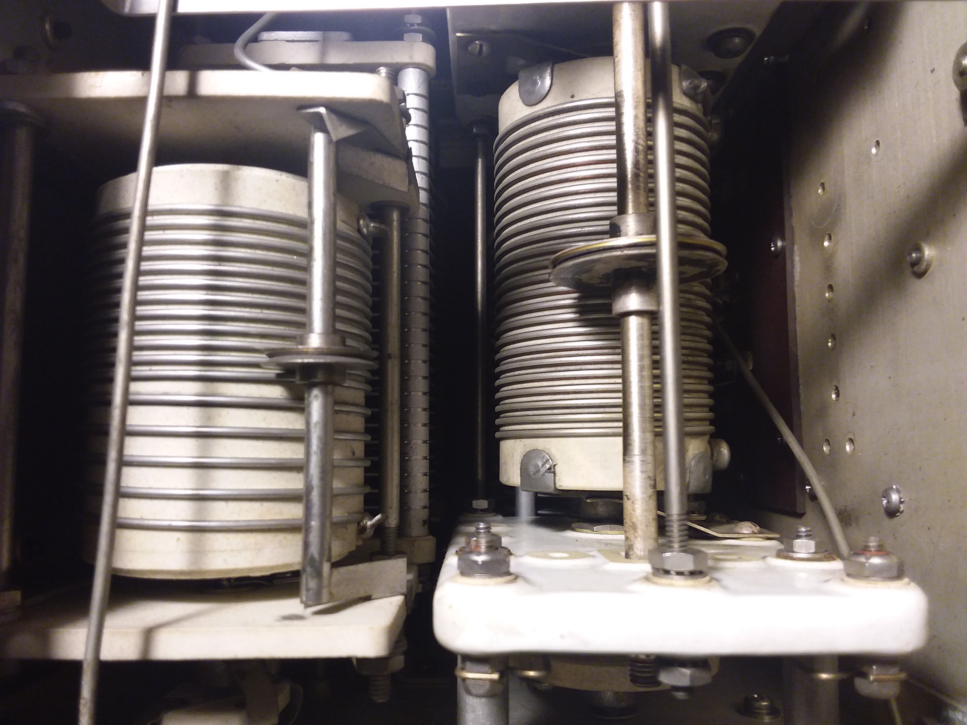 The inductor rollers adjusted and sitting at resonance for 40 meters |
|
These dials are one of the weak links in restoring a KWS-1. They are made of half pot metal and half aluminum. (I have a 90 year old Atwater Kent with pot metal rollers that literally fell apart in my hands as I pulled them off a shaft) There is a tiny brass gear inside the knob which makes contact with 2 tiny gears on the shaft with tiny teeth. Overtime the knobs become deformed by cranking down on the set screw to keep proper contact with the control shaft. This is especially true for the Tune control which requires a lot of torque to turn the roller inductor. Needless to say these 65 year old knobs are no longer made anywhere. WBear2GCR has an extensive write up about repairing these things. And it's not easy. I can feel the extra tightness in the Tune control compared to the Load control, and I wondered if it would be a good thing to remove the PA cage and do some quality cleaning of the shafts and gears. I've dealt with stiff gearing on my R-390 and doing a thorough cleaning of the gear assembly really made a difference in working the Kilocycle control. But I don't have a feel for whether the Tune control on this KWS-1 is in need of immediate attention. It's certainly stiff, and you feel an occasional bump as you slowly make your way through the gearing. But there's no slippage. It just takes a long time to get from 80 meters to 10. I'll put the gear assembly on the back burner for now and first see if I can finally get some output from this thing. |
|
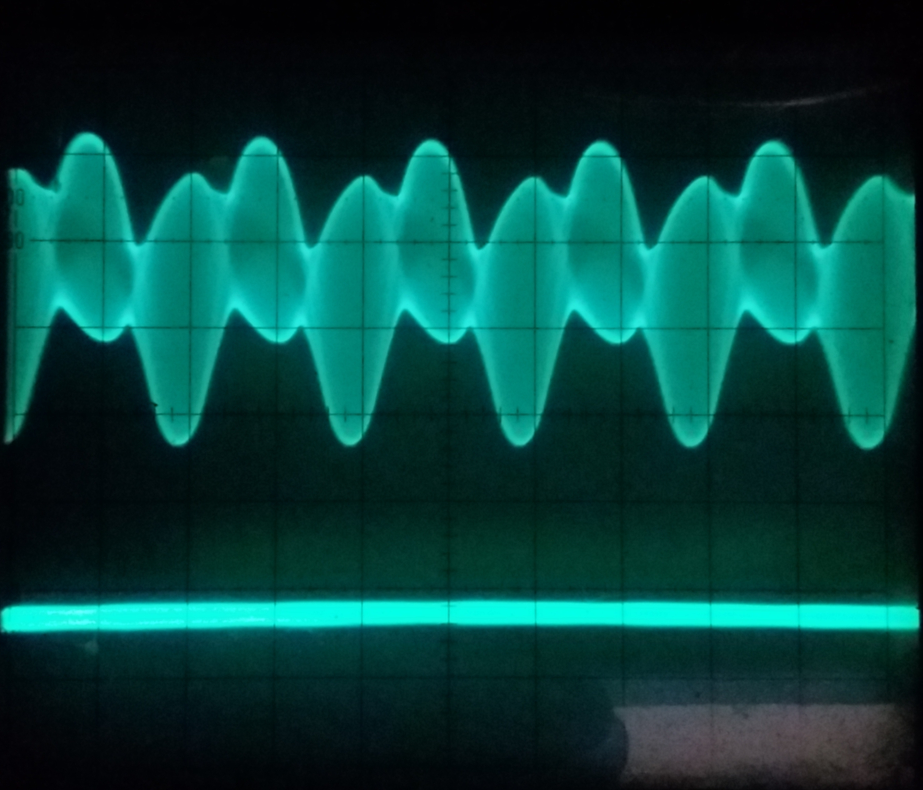
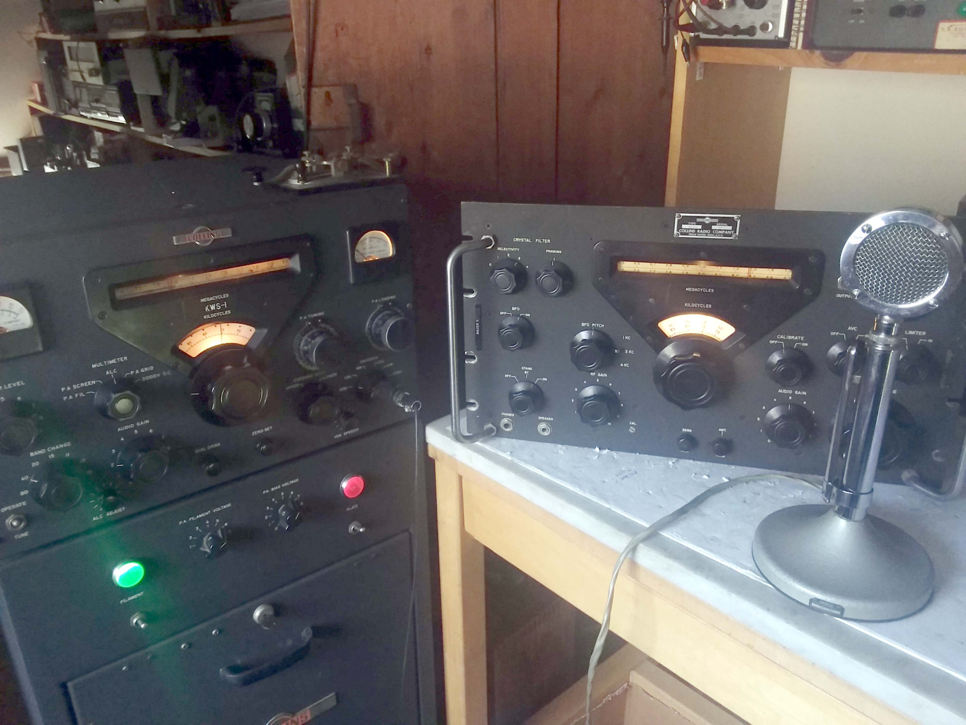
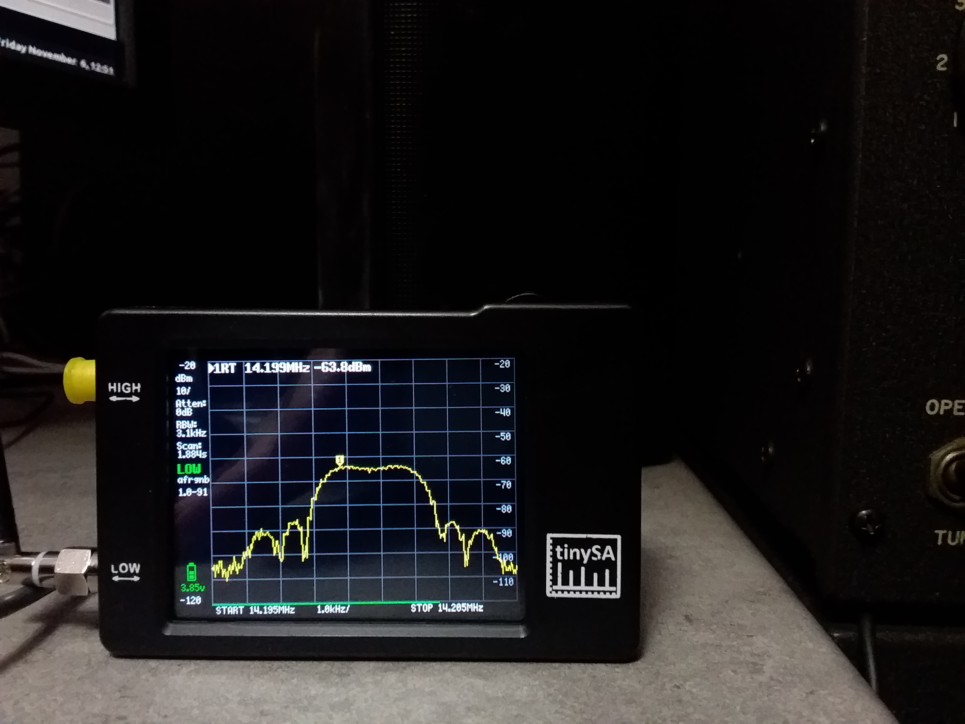
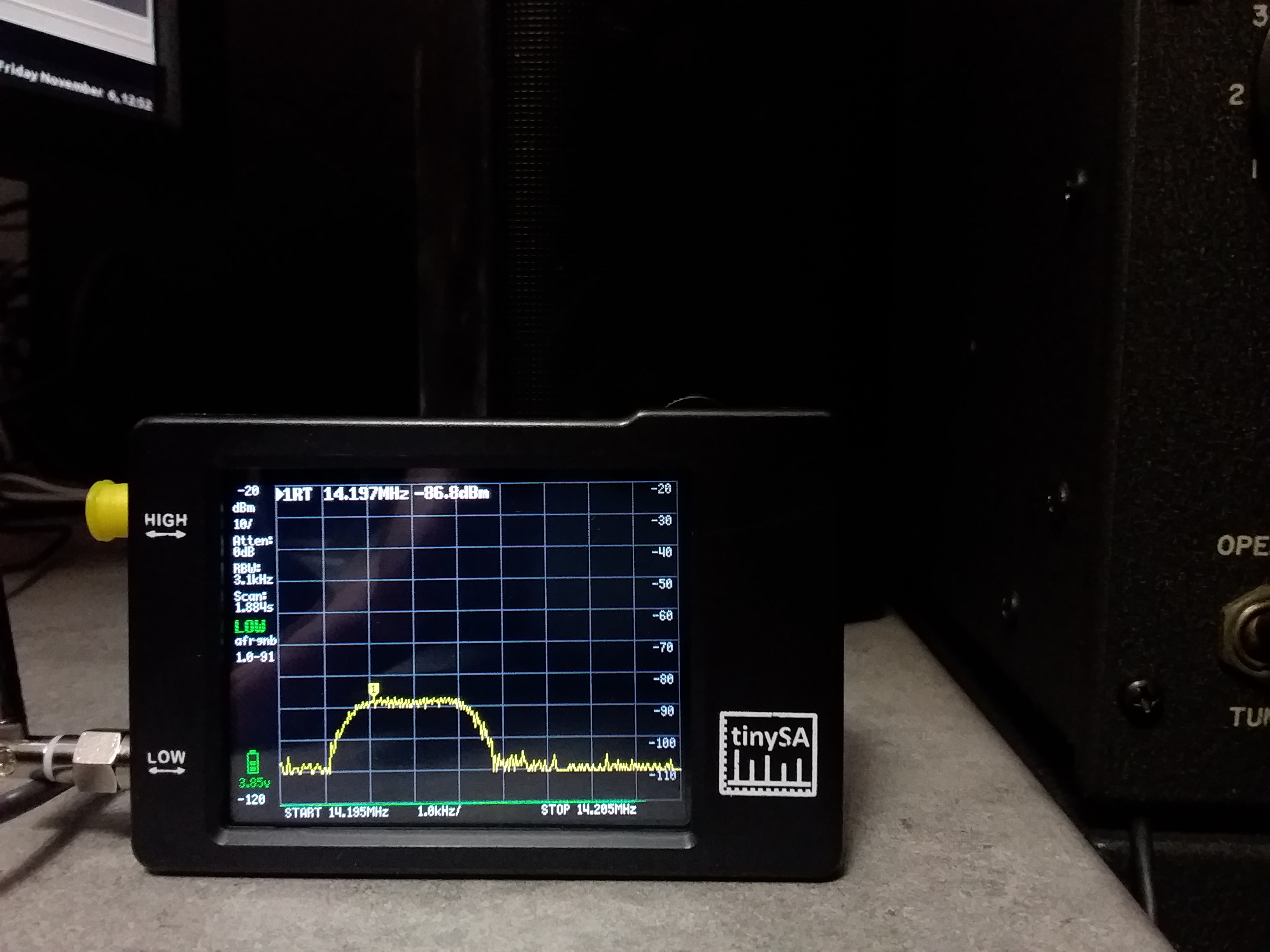
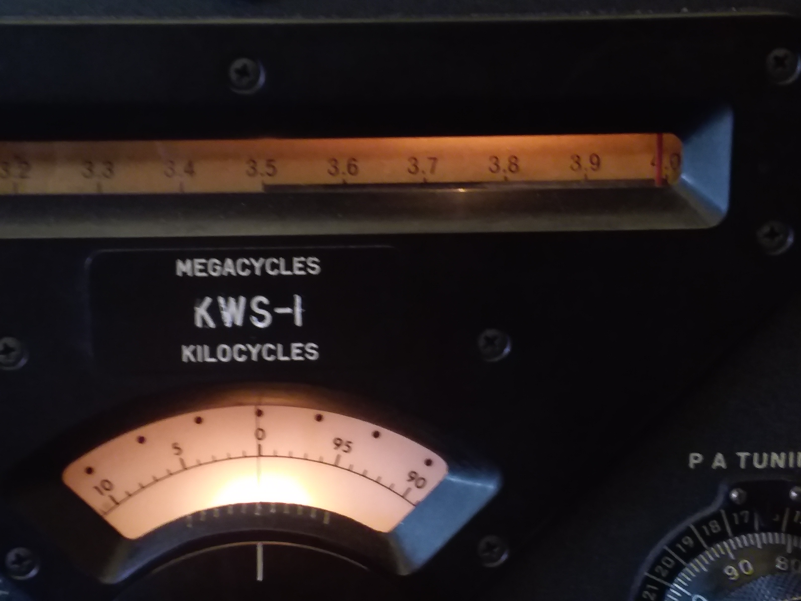
Output On 10 and 80 I tuned up on 10 meters again and was able to see 30 watts output. But tuning was not very sharp. And the heaviness of the Tune control made it difficult to get a feel for what exactly was going on. I moved down to 80 meters. Very slowly. Here at 3.9mcs I was able to load up to 400mA with 150 watts output showing on the old Waters 334 wattmeter. I have no idea what shape the final tubes are in. But I've got something to work with now. |
|
Oh By The Way, This Fell Out Of The Rig |
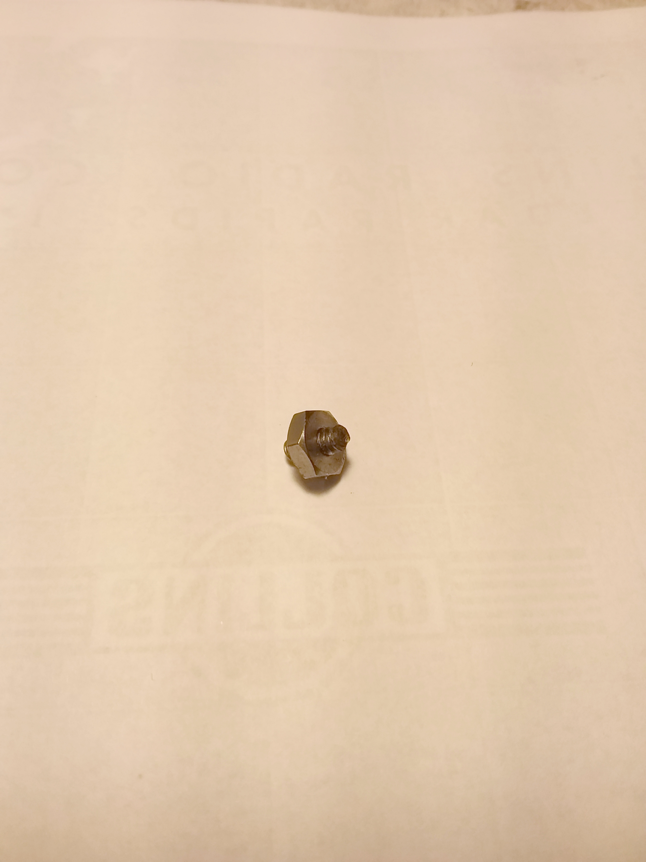 Unidentified loose metal rolling around the bottom cover |
|
It looks like a piece of one of the roller inductors? I hope not. |
|
VFO Alignment - 11 Nov 2020 As long as the KWS-1 was back at the bench I decided it was time to do a preliminary overall alignment. I got the book out and started with the VFO alignment. Tracking from one end of a band to the other was not great. It was enough work getting used to spotting the KWS-1 with the 51J-4 but I was also having to CAL the transmitter every 100 kc to keep track of where I was. I've had some experience with VFO endpoint calibration with my R390. So I was prepared mentally to do battle with this particular PTO. But I was quite pleased to find that unlike the 70H-2 PTO used in the R-390 the KWS-1 uses a 70E-23 which has an outboarded, somewhat accessible Endpoint Trimmer stud. With the R-390 you could only access the trimmer by unscrewing that plug located just to the right of the trimmer stud. And you needed a very long thin screwdriver that would fit through the hole on the front mounting plate to make the adjustment. Which of course meant you had to remove the PTO from the receiver to do it. That part of the R-390 rebuild was a very good learning experience for me but I am very glad that this PTO is serviceable from within the rig. |
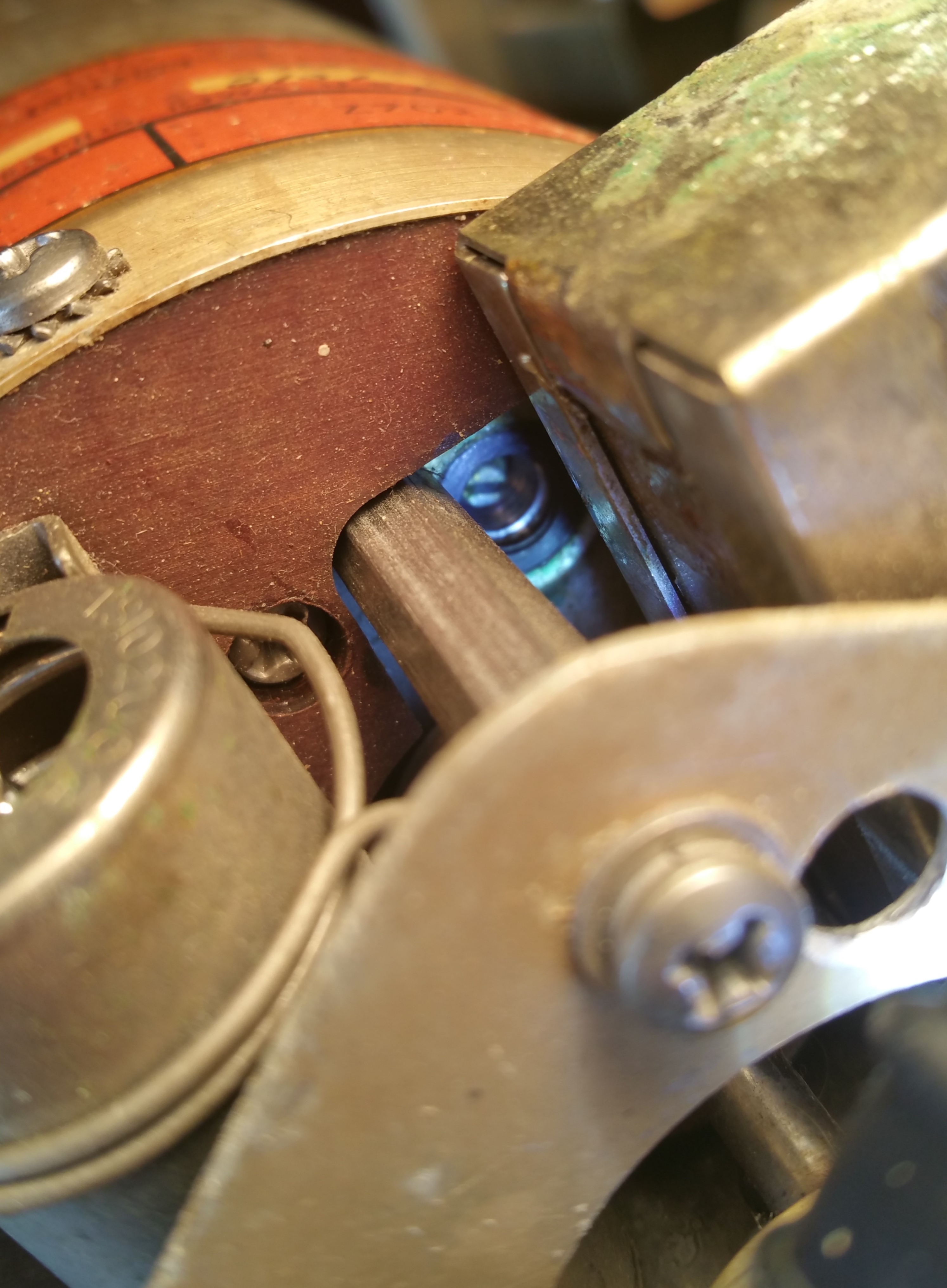
 R-390 vs. KWS-1 PTO |
|
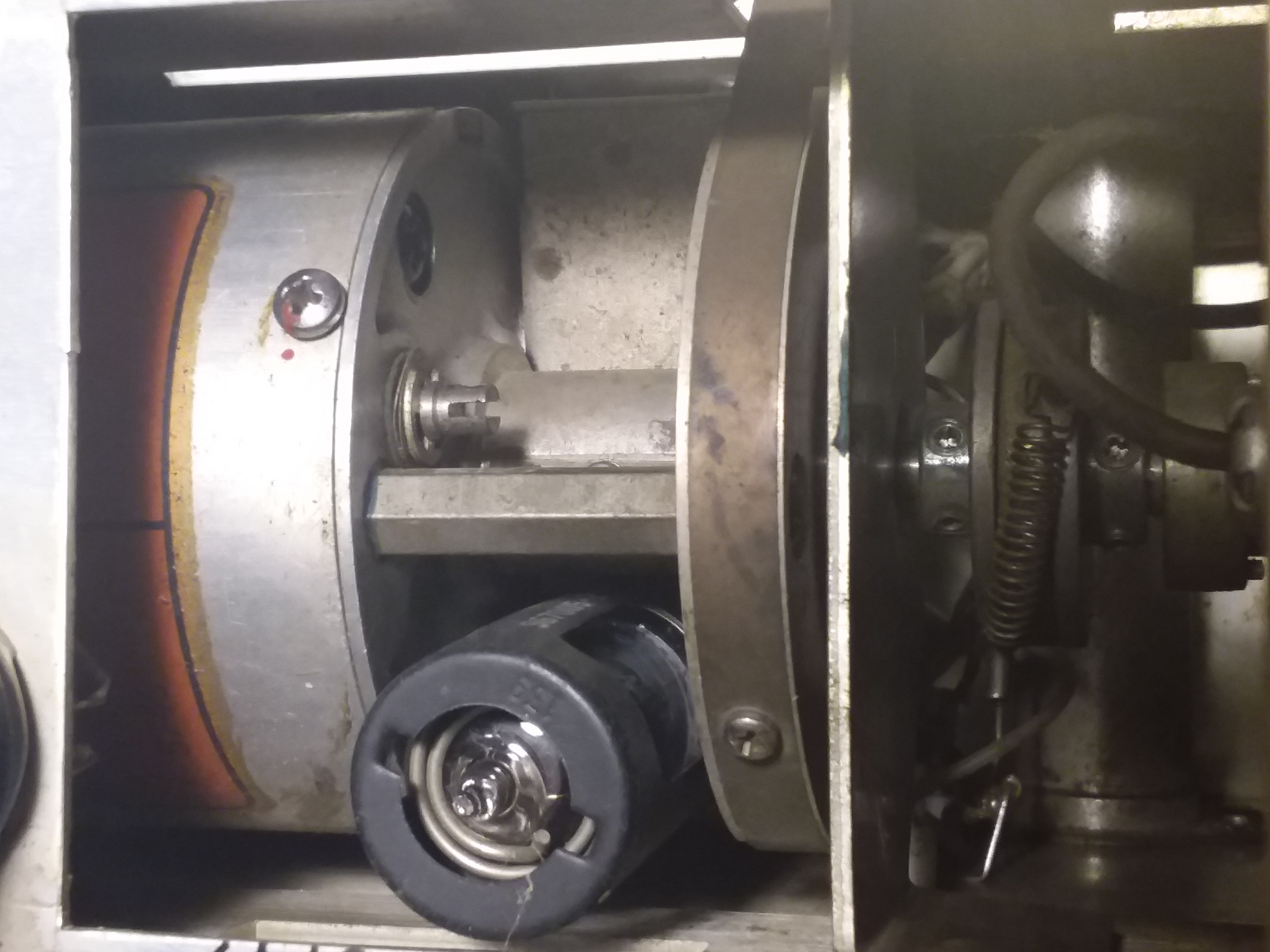
I started at the low end of 80 meters at 3.0mc and I used my Japan Radio Co. NRD-535 receiver to make the adjustments. 10 turns of the PTO only brought me to 3.92mc on the upper end. It was a little tricky finding the right tiny screwdriver to fit in the stud hole and slot and I used a pair of pliers as gingerly as I could to turn the stud when the hole or slot were out of reach. But a few times back and forth and I was able to make up the 8kc difference. Unfortunately the Zero Set had run out of room on the lefthand side and needed to be readjusted. I had to search the toolbox to find the right sized Bristol wrench to get in on the VFO dial coupler. With the VFO set to 4.0mc I loosened the dial knob coupler setscrews, moved the dial shaft for zero beat in the NRD-535, turned the fiducial dial to zero, straight up and then tightened back down on the setscrews. 4.0mc = 0. |
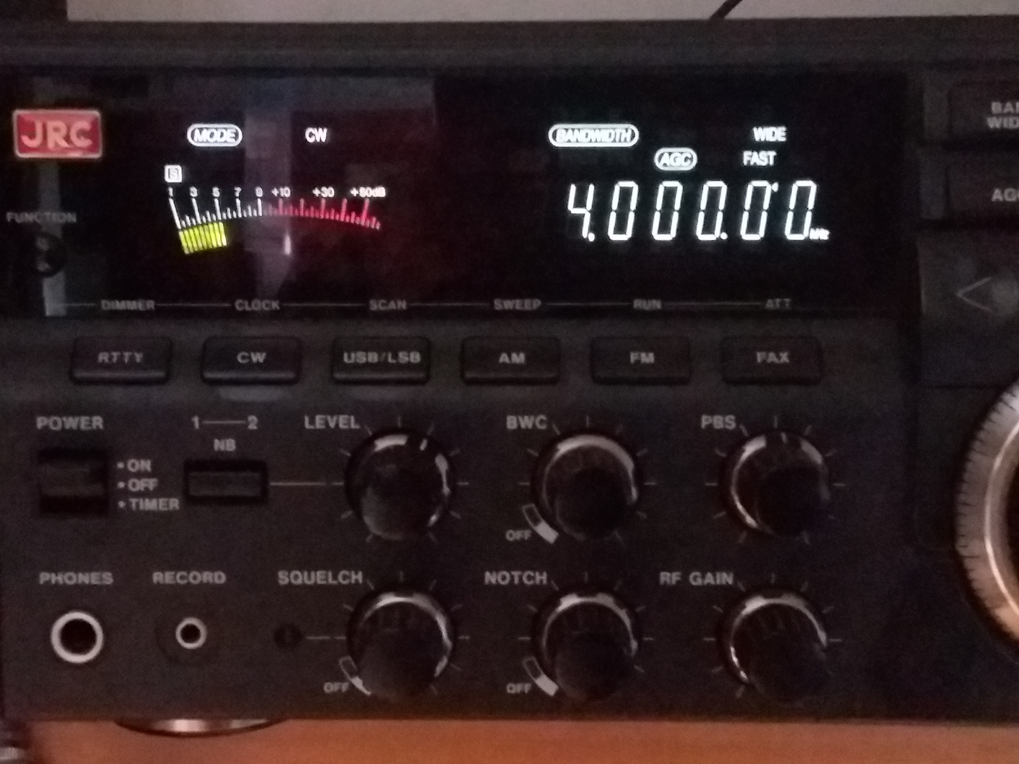
 Using the NRD-535 to calibrate the KWS-1 VFO |
|
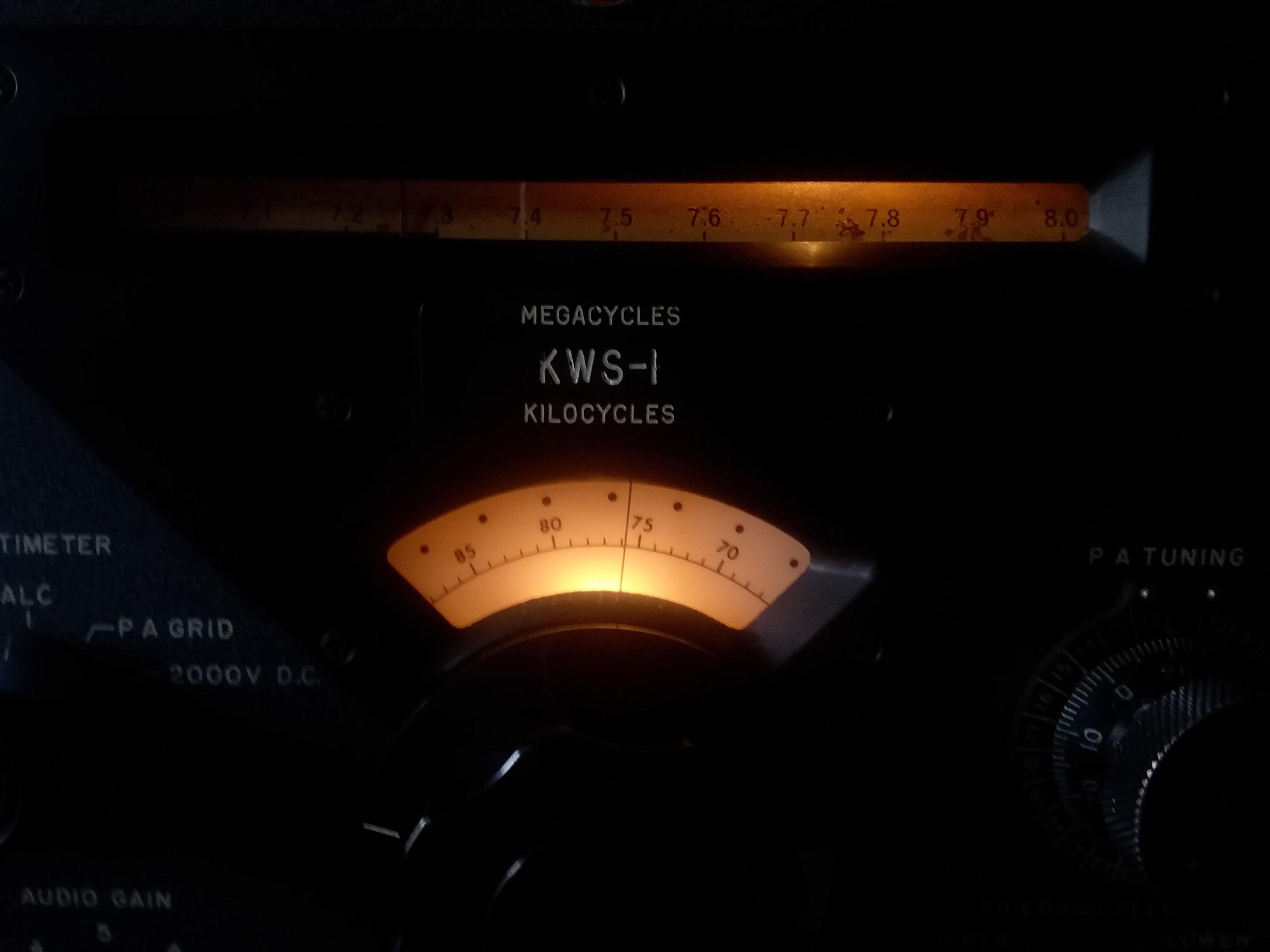
The Megacycle dial is off about 100kc. No big deal really, but it does bug me that the pointer is not sitting exactly on the 4.0mc mark. I'm not sure if that's a Megacycle dial vs. Fiducial plate thing or a simple adjust the Megacycle dial pointer thing. A detail to worry about later. |
 2020 WA2FXM - Mark Mohrmann 2020 WA2FXM - Mark Mohrmann |
 |