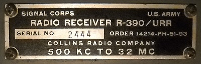
| Another R-390/URR |
|---|
|
|
| The Rebuild | |
|---|---|
|
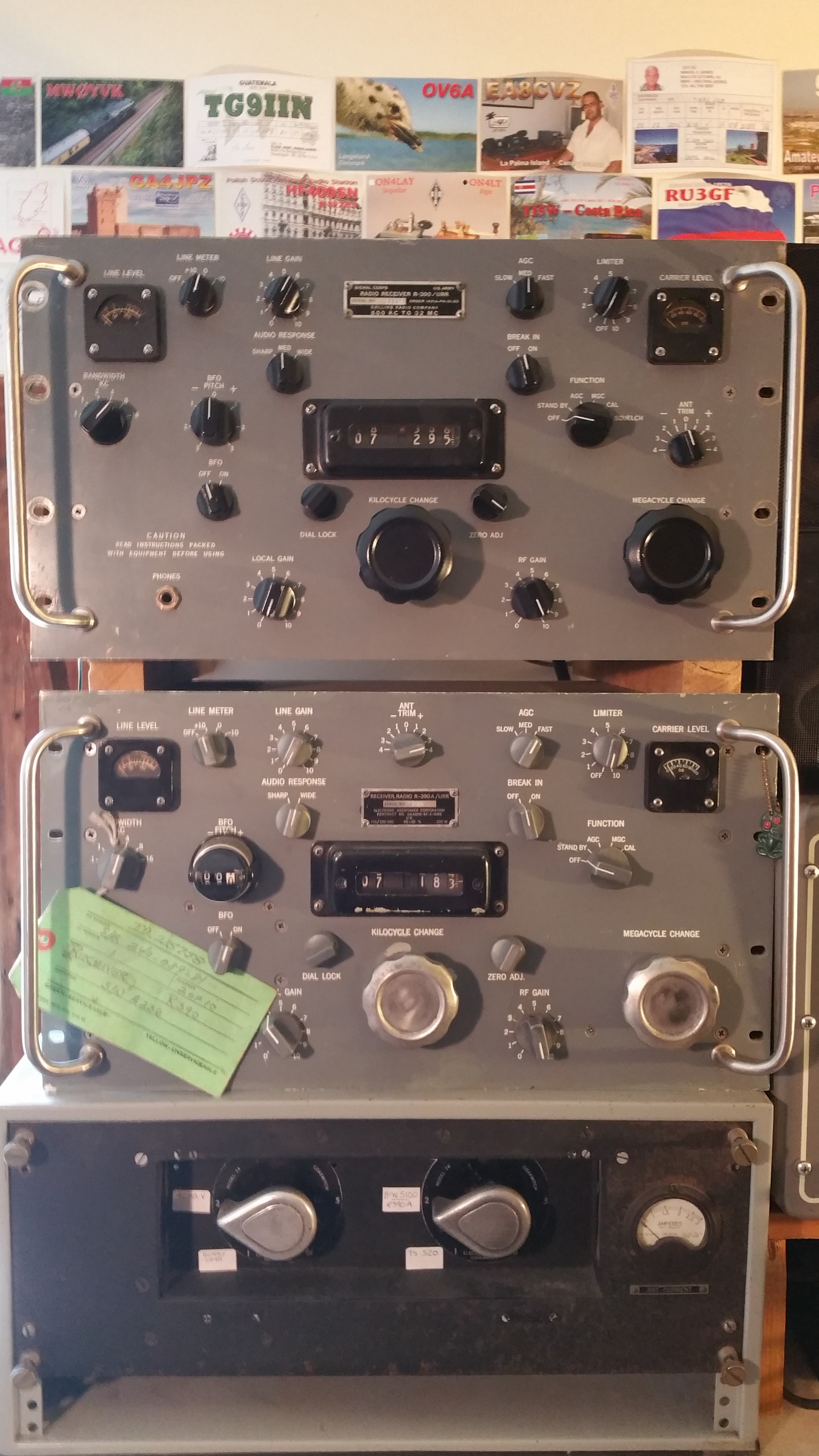
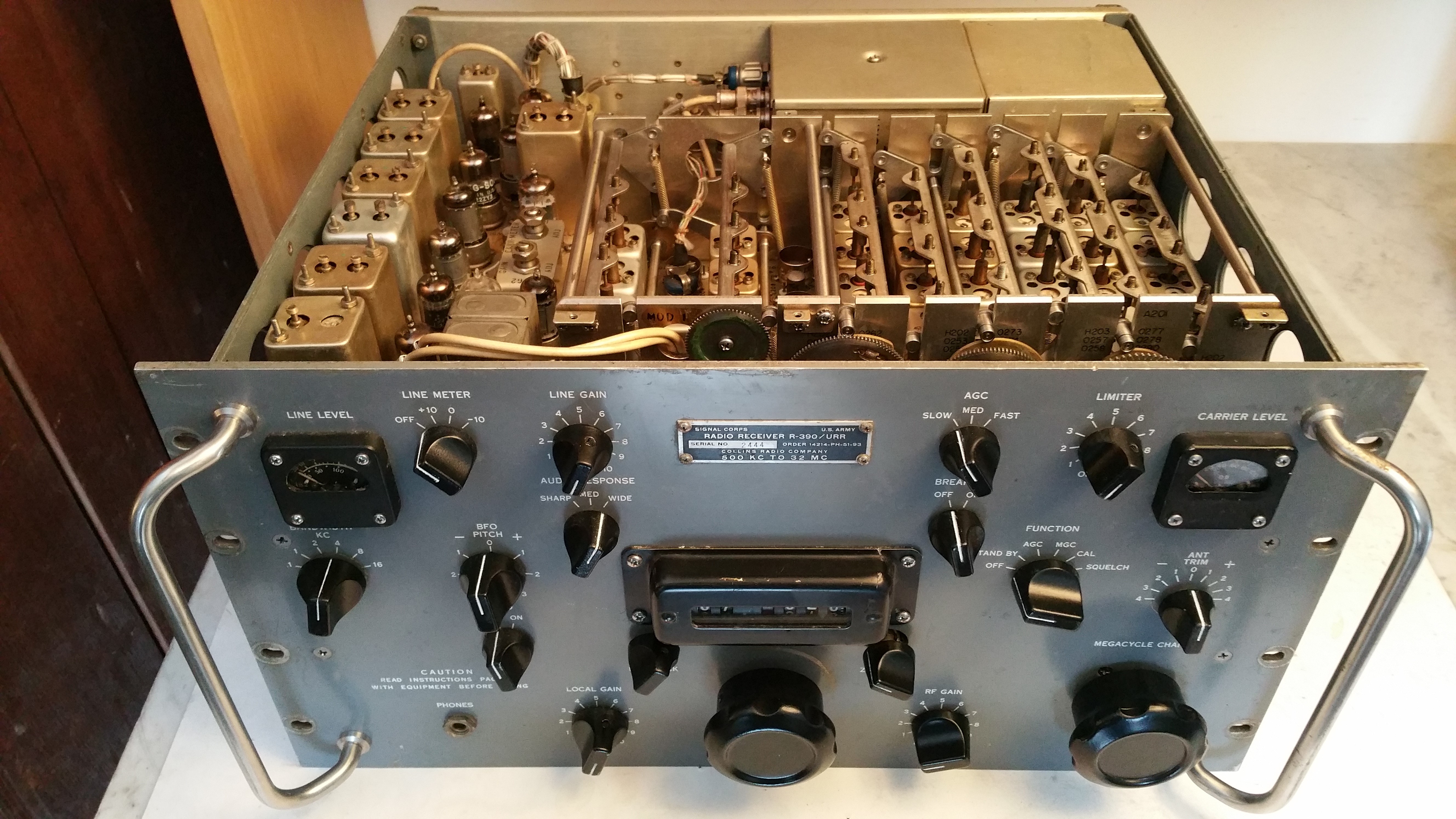
Done. For Now - Aug 7, 2017 Finishing up on some loose ends. The Zero Adjust adjustment needed readjusting. I had the Kilocycle Dial set wrong when I reinstalled the RF Deck. For some reason I chose -972 instead of -965. Off just enough to keep the Zero Adjust out of range. I loosened the Kilocycle Dial bevel gear clamp and reset the counter. All is well. I could continue on. There's more to be done. I need to find a logarithmic taper RF Gain pot to replace the linear one I threw in there. There's the fan to outboard to cool off the 6082's. Then the solid state rectifier mod. And I never did go back and reinstall the RF Deck with the proper 2 teeth tensioning on the split gears. I think I can feel that too, that might be a nice operating improvement. But for now, I'm done. It's sitting on top of the EAC R-390A and it's outperforming it too. I'm going to venture that this is the best performing receiver I have ever owned. |
|
 |
|
|
It's Fixed, But Not Where I Thought - Jul 27, 2017 I have a tendency when working on ham and ham related equipment to assume a fault is due to some esoteric problem buried deep inside the radio that will require some very arcane amateur radio electronic theory to fix. My first reaction is to grab an old ARRL Radio Handbook and start reading about vacuum tube and radio circuit theory so that I will be prepared for the upcoming battle with the radio. My gut knows that you should check (and double check) the simple stuff first, but my brain says 'Go read a book and then you'll know what to do'. My lack of knowledge about the R-390's frequency conversion scheme didn't keep me from fixing the problem, but it did lead me astray into thinking there were problems in obscure places instead of checking for some simple solutions first. What I thought was a drop in gain at the 2nd mixer was just me trying to inject a signal in the wrong place. Jacques VE2JFE, sent me to school on the frequency conversion scheme. After it made sense to me I was able to start again checking out the stage gains with the proper signals. |
 |
|
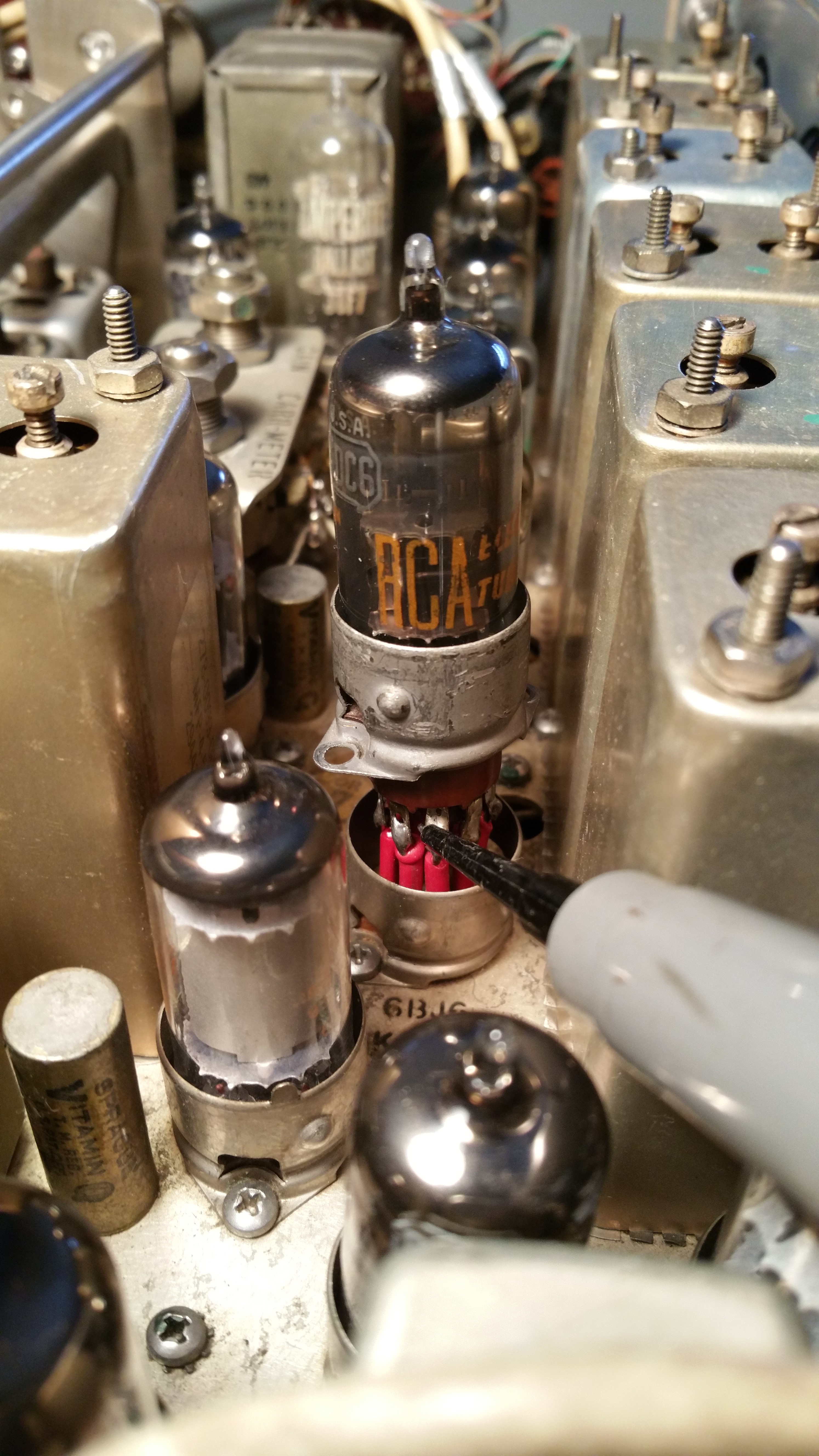
It turns out that the mysteriously "good" 6DC6 tube that I was using back in April as a 6BJ6 sub, which would not work in the IF unit found it's way into V202, the 2nd RF Amp. With no more spares to go around I stuck it in there, ordered some new tubes and then forgot about it when the tubes showed up. Well the 6DC6 doesn't work in the RF unit either. My "trusty" old TAB Tube Substitution book is not so trusty anymore. I pulled the 6DC6 out, put in an original Hoffman "Easy-Vision" 6BJ6 and the radio came back to life. |
|
Closing In On The Sensitivity Problem? - Jul 14, 2017 It looks like there's a problem somewhere in the 2nd or 3rd mixer circuits. 50uV of 455 kHz IF signal is getting through the input to the 3rd mixer tube at E210 sometimes, but other times it just goes into some kind of oscillation with the signal generator lead clipped on. And T207 is maxxed with the slug all the way out as far as it will travel. At E209, the input to the 2nd mixer tube, the sensitivity is way off. 4500 uV at 2.4mHz to get the -7V DIODE LOAD reading. Both tubes checked good and swapping them out made no difference. All tube voltages are good. |
|
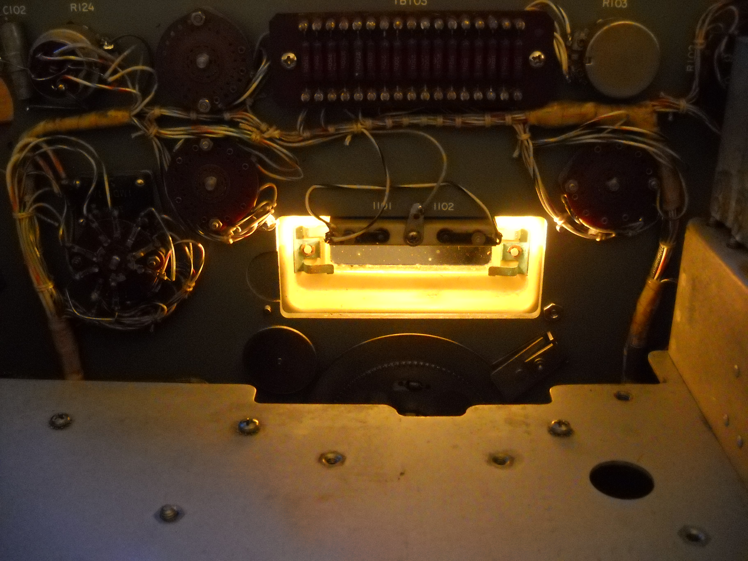
Voltage Regulation Fixed - Jun 3, 2017 Problem solved with a little help from Don WC4G and Jacques VE2JFE. The regulated voltage shot up to 280V because the DC Amplifier tube VR 607 wasn't doing it's job which is to control the voltage drop across the 6082's. VR607 was disabled because it lost its filament voltage. It's part of a filament chain that includes audio tubes V603 and V604, and V509 on the RF deck. V509 opened up, and I never noticed that the 3 tubes on the Audio unit were dark. With the unit laying on it's side I couldn't get a good view of the filaments, so I measured the full 26V at V607's socket and thought all was good. But I didn't think it through enough. V607 is the first tube in the chain so it's going to read 26V whether the filament chain is good or open. |
 |
|
So, my eyes and my logic failed me this time. But being slightly inobservent has it's advantages. I was able to replace 2 old capacitors in the Audio unit while hunting around for the problem. I was able to stock up on spare tubes for the VR circuit. And I learned a lot about how it works, and what to look for when it doesn't. |

|
|
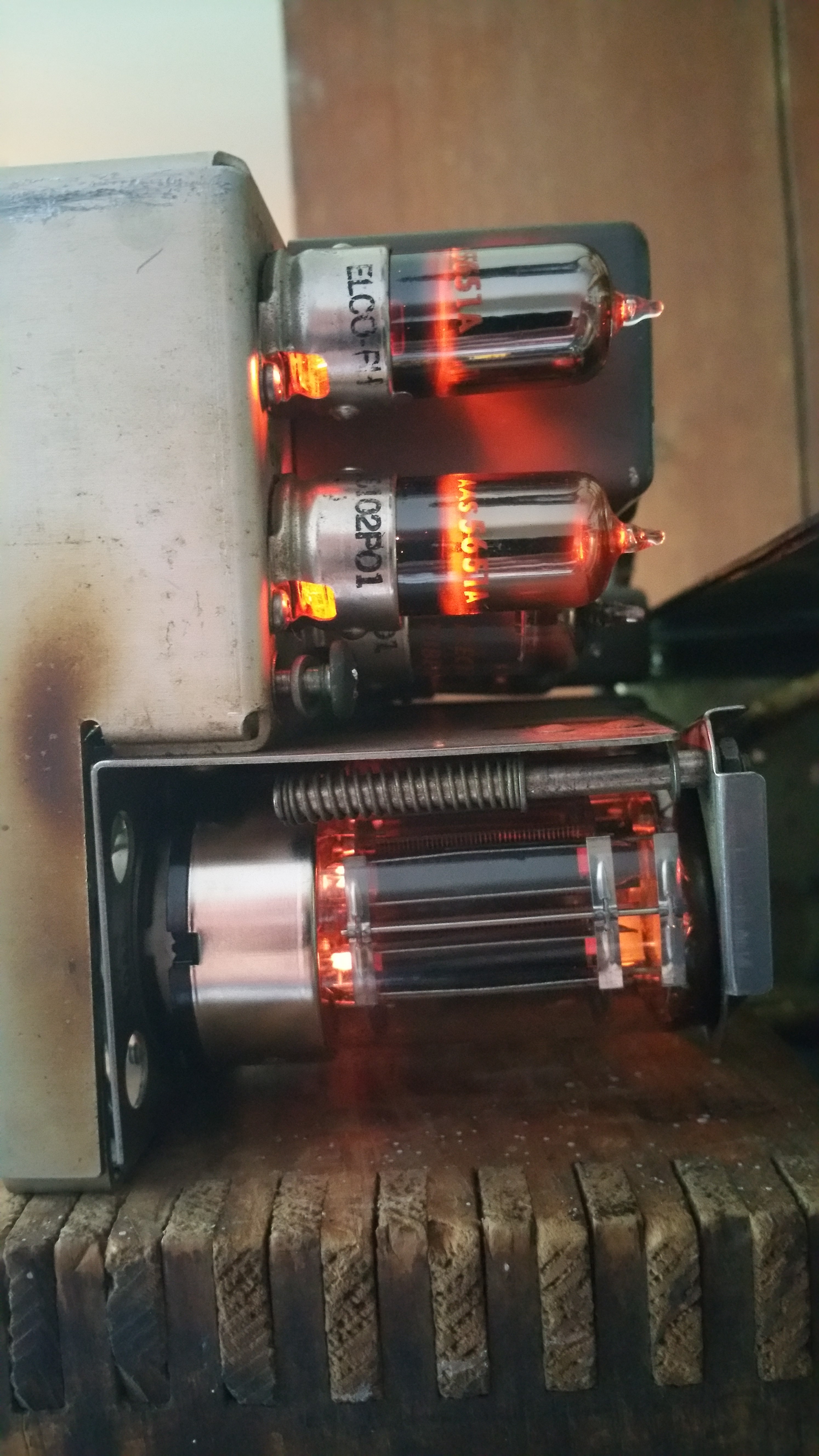
In normal operation the 2 voltage reference tubes turn on brightly for a few seconds and then the glow diminishes. With the voltage sitting at 280V the tubes turn on and glow brightly all the time. And you would think that the reference resistors R625 and R626 would be fried. In fact the first things I ever replaced in this radio were these 2 resistors because they were way high in value. But somehow the new ones survived all that current and are still good. |
|
Lost Voltage Regulation - May 12, 2017 In the middle of trying to get a handle on the Stage Gain characteristics of the radio, it suddenly lost it's 180V regulated voltage. One step forward, two steps back. |
|
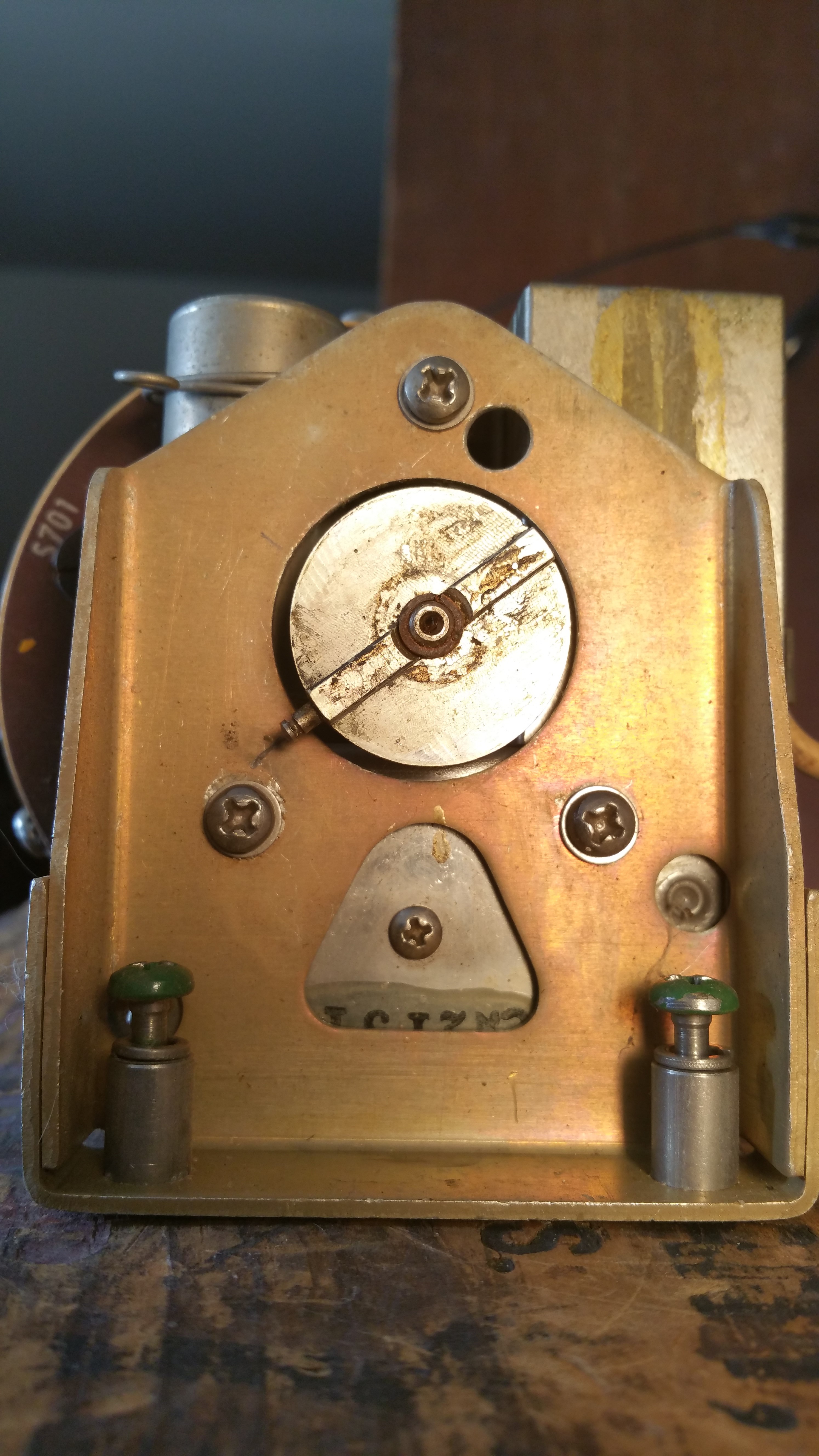
PTO Endpoint Alignment - May 4, 2017 |
|
 |
|
|
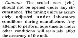
The R-390 Maintenance Manual is very clear when it comes to PTO maintenance and adjustments. Don't f*** with the PTO innards. And while you don't have to open the sealed can to make the endpoint adjustment you do have to poke around with a tweaker inside the can. And the fact that no where in the Manual do you get any guidance on doing this might lead one to conclude that you take your life into your hands if you try. But I was determined to demystify the PTO in my own mind and with a little help from Dave Medley's words of wisdom and from some other R390 fellow travellers I was able to get a decently accurate readout on the kilocycle dial. |
|
 |
 |
|
I decided to first do a practice run on the PTO from the junker R390. I set it up on a box, close enough to the radio that I could plug it in for power, with the output going to a frequency counter. So, exactly where is this adjustment? Peering into the front end of the PTO assembly, behind the only round hole opening which you could possibly stick a screwdriver through I could see an unlabeled, green painted, slotted hex screwhead. Must be the access cover screw that Dave Medley cautions you not to lose. I removed the VFO tube from it's socket so that I could get in there with my fingers to remove the screw once I had it backed out. I put the tube back in, powered up the radio and let it sit for an hour to warm up. While the PTO was warming up I played with it. Fully clockwise it was running at 2.241 mc. It took about 2-1/4 turns to get up to 2.455 which is where the +000 setting for the kilocycle dial would be. I counted 15-1/4 total turns to the high end where it was at 3.693 mc. With the thing all warmed up I turned the shaft back to the 2.45500 mc spot and marked it with pencil on the front faceplate using the oldham coupler spring post as an index. |
|
 |
 |
|
I then turned the coupler and shaft counter-clockwise exactly 10 times and set the post at the pencil mark. The counter read 3.44511. I was 9.89 kcs off. This is where the endpoint adjustment finally comes into play. I stuck a screwdriver through the hole into the adjustment slot and turned it until the counter read 3.455. Now, turn the shaft clockwise again, back down until you get to 2.455. You find that the position has moved a little from your penciled index point. This is good. Your adjustment is starting to take hold. You mark the new 2.455 position and you repeat the process. Each time I did this the kilocycle error was basically cut in half. By the 6th time around I had gotten the error down to about 700 cycles. That was about the best I was going to get just eyeballing the thing. So at this point I'm pretty proud of myself. I've taken on the PTO and it seems to have responded the way it was planned. A lot of the mystery for me disappeared as soon as I set the PTO on the box, by itself, disconnected from the Kilocycle Dial mechanism. It suddenly hit me that the PTO doesn't care where your RF Deck cams, 10-turn counter and Kilocycle Dial are sitting. The alignment happens independent of these 3 variables. You do have to take care when you re-install the PTO to align things properly, but the PTO itself is just another blackbox that you align and then plug into your system. And so it was that in attempting to plug the PTO back into the system I discovered a 4th variable I hadn't thought about. The positions of the oldham couplers on the PTO and the Kilocycle dial must also be in proper alignment so that the oldham disk will mate with both couplers. The only way I know of to mount the PTO back into the radio is to angle it into position while holding the back of the oldham disk against the PTO coupler and sliding the front disk groove into the Kilocycle Dial coupler ridge. This can only happen if the Kilocycle Dial coupler ridge is in a horizontal position (with the radio laying on its side). This means that the PTO coupler ridge must be in a vertical position (with the radio laying on its side). Something I did not account for when I was finished aligning the PTO. I thought the easy fix was to make sure the PTO and Kilocycle Dials were in their proper positions. Then loosen the clamps on each one and re-position the oldham couplers to their proper positions, tighten the clamps and everything would be fine. This was almost the case but not quite. |
|
 |
 |
|
The Kilocycle Dial clamp loosened easy enough and I reset its coupler position. But either the shaft on my PTO is incredibly gunked up with stuff or there is some type of a fiber ring that its oldham coupler clamps onto. The clamp was stuck to the shaft and I needed a pair of needlenose pliers to move the shaft while trying to hold the coupler in its horizontal position. To do this I first had to remove the front mounting plate to make room for the pliers to get at the shaft. It was pretty awkward trying to get the shaft at 2.455 mc with the pliers while trying to keep the coupler horizontal with my fingers. It took a couple of tries to get it right. Finally I tightened up the clamp, and remounted the front mounting plate. Remembering the access hole cover screw, I pulled the VFO tube and reinstalled it in the adjustment access hole. Put the tube back in, reinstalled the PTO and watched the oldham disk slide easily past the Kilocycle Dial coupler ridge. |
|
 |
 |
|
So how good was this non-precision-jigged, eyeballed PTO alignment? With everything back in place I turned the radio on and found a broadcast station at 530. I zero-beat it and fixed the Kilocycle Dial at exactly 530. I spun up to 1000 and zero-beat the station there. The dial read 1002. I moved up one band, started at 1000 and got 1701 on the last station at the top of the band. I'm still having problems with the CAL signal, but I do get a very weak signal on some of the upper bands. I went to the 7 mc band at 7500 and zero-beat the CAL signal there. At the top of the band I got a CAL signal at 8001. At the bottom 6999. I can live with that. |
|
|
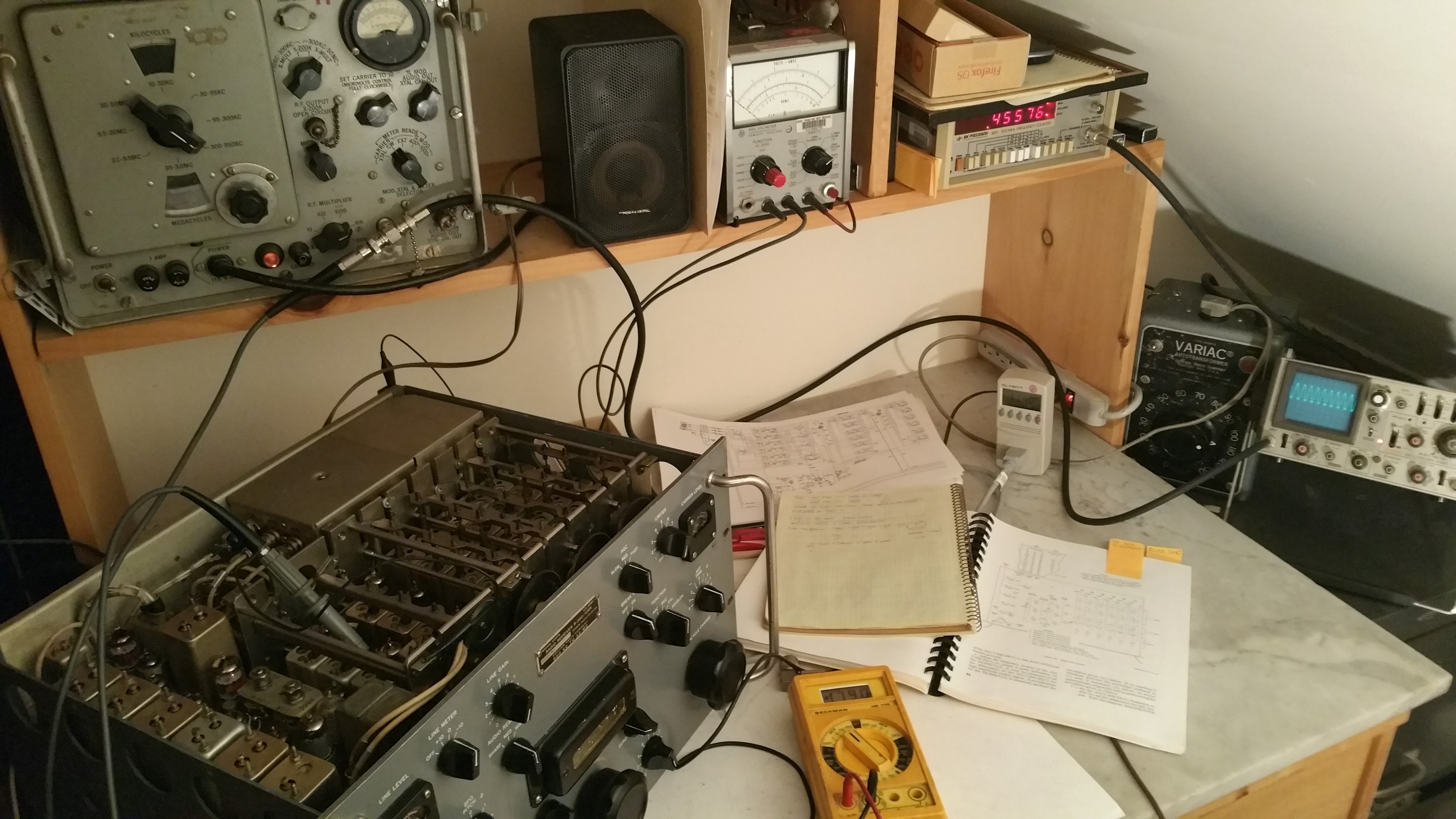
RF Alignment - April 27, 2017 Going through the RF alignment one set of bands at a time you can feel the radio come to life. Tweaking the coils at 600, 900 and then 1100 and 1900 and the broadcast band at night is absolutely alive. On 160 some strong CW and a few sideband signals off of the 265 ft. random wire antenna that stretches out across the swamp to a tree on the far hillside. Moving up through the slug racks, on 80 similar reception, and going all the way up to 12 mc all the SW and amateur bands showing life at night. This morning results not as spectacular on the higher bands. As a matter of fact on all bands, doing an A\B switch between the R-390 and my original EAC R-390A using the random wire and the 40 meter vertical I can see that the R-390 still needs some work. The EAC has been neglected for a long time. I haven't had it opened up in about 15 years but it is definitely outperforming the Collins after the first round of alignments. Maybe now is the time to step back and see about finally getting the PTO endpoint adjustment done. Then we'll test the limits of the AN/URM-25 and see if we can do a proper Stage Gain check to see where the sensitivity may be falling off. |
|
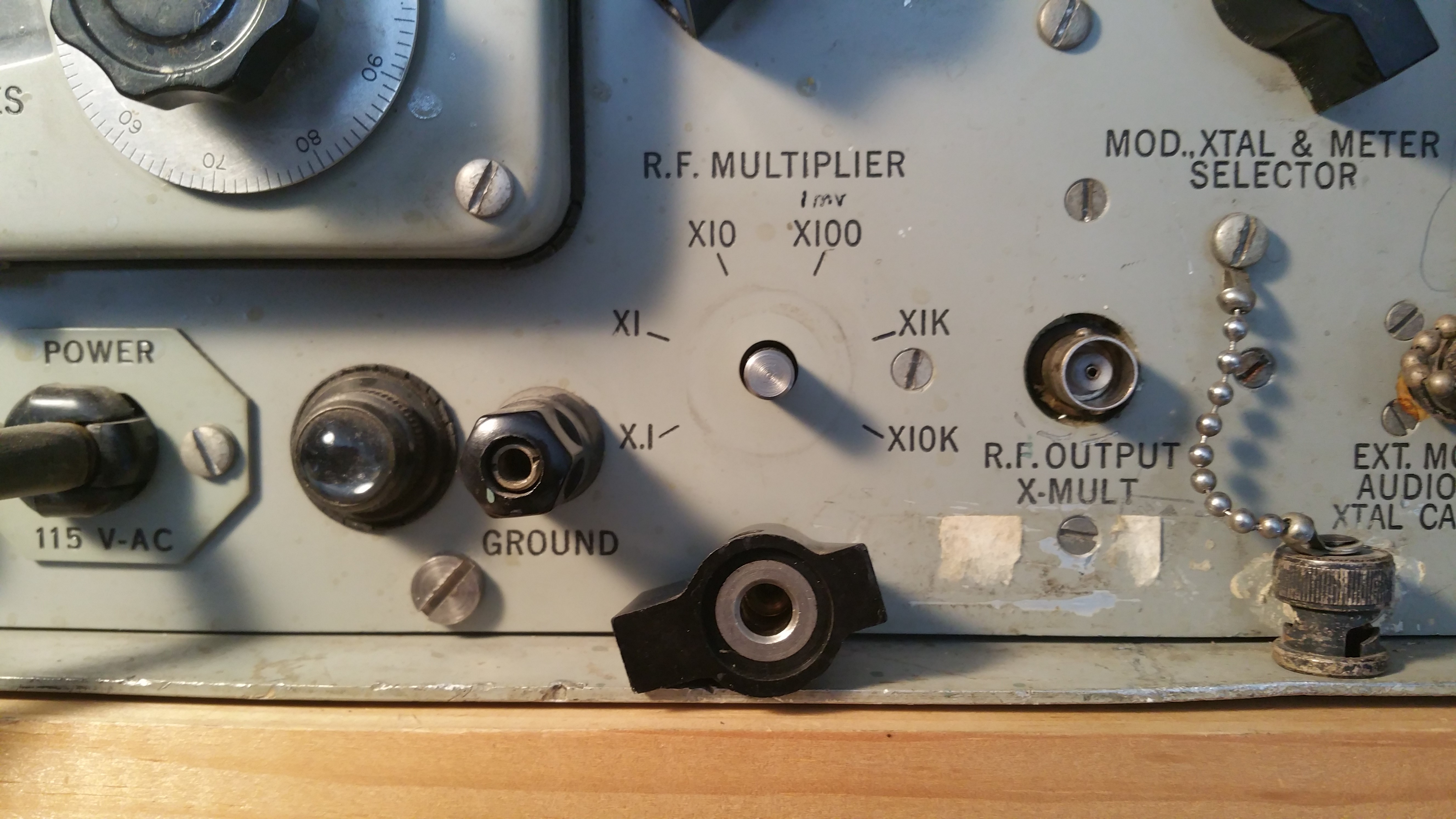
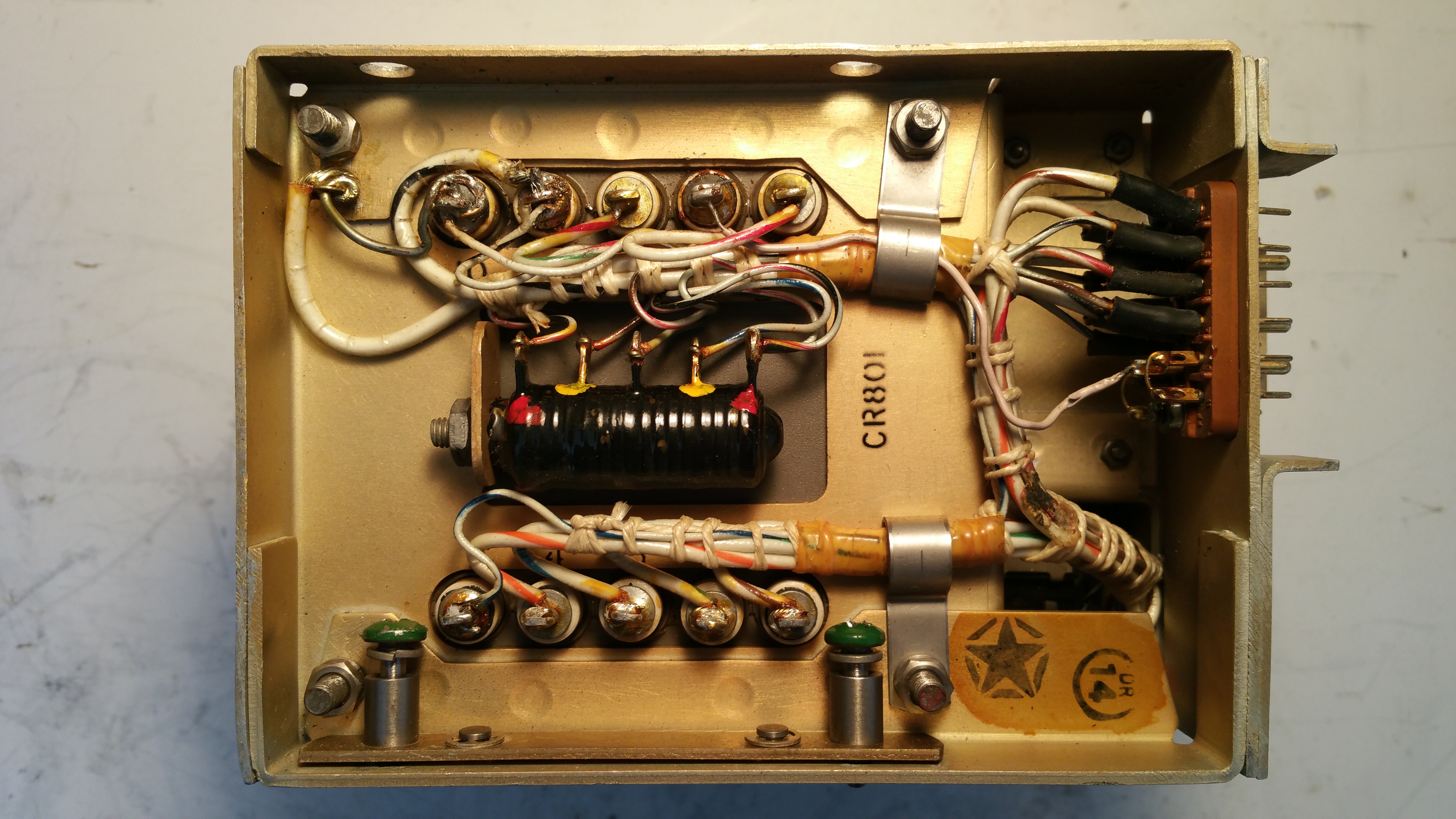
Another AN/URM-25 Detour - April 26, 2017 |
|
 |
|
|
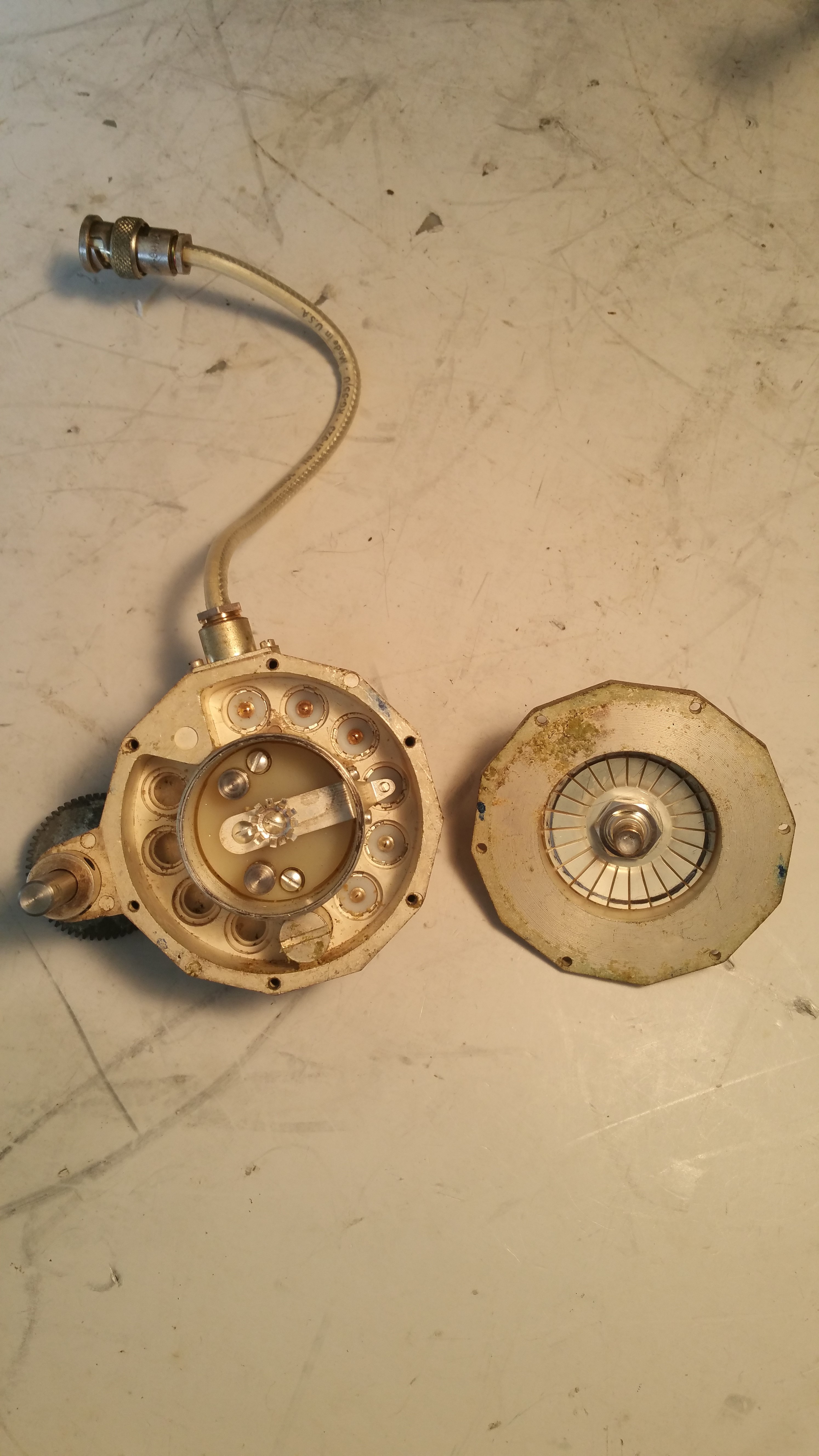
Working my way through the RF alignment. BCB, 160 and 80 meter bands are coming alive. Things were going pretty well until the knob on the AN/URM-25 Step Attenuator started slipping. Except the problem wasn't in the knob, which was fastened tightly to the switch shaft. I pulled the generator down from the shelf and opened it up and saw the problem was on the attenuator gears. The attenuator switch has a fair amount of torque to it and the set screws on the gears are not up to the task anymore. The switch shaft is deeply scored and the hex socket heads on the set screws are stripped. I'm guessing I'm the most recent in a long line of techs who have tried to crank down on the screws to keep the gear from slipping. |
|
 |
 |
|
A quick trip to the Pick & Shovel hardware store last night and I came back with some brand new 6-32 set screws. While I had the attenuator box opened I cleaned the contacts and the wiper. Put it all back together this morning and we're back in business. | |
|
AGC, IF, and Crystal Oscillator Alignments - April 24, 2017 AGC and IF alignment seemed to go pretty well except for the Z501 Crystal Filter. Z503 peaked OK for the AGC, and I got good gain increases from tweaking the IF amps, variable IF amps and the 3rd Mixer coils. But I got inconclusive results around the Crystal Filter Z501. For the 2nd Crystal Oscillators I got large increases in all of the bands except one. The 22 mc trimmer felt loose compared to all the others and had no effect on the test point voltage. The 1st Crystal Oscillators were all basically fine where they were. |
|
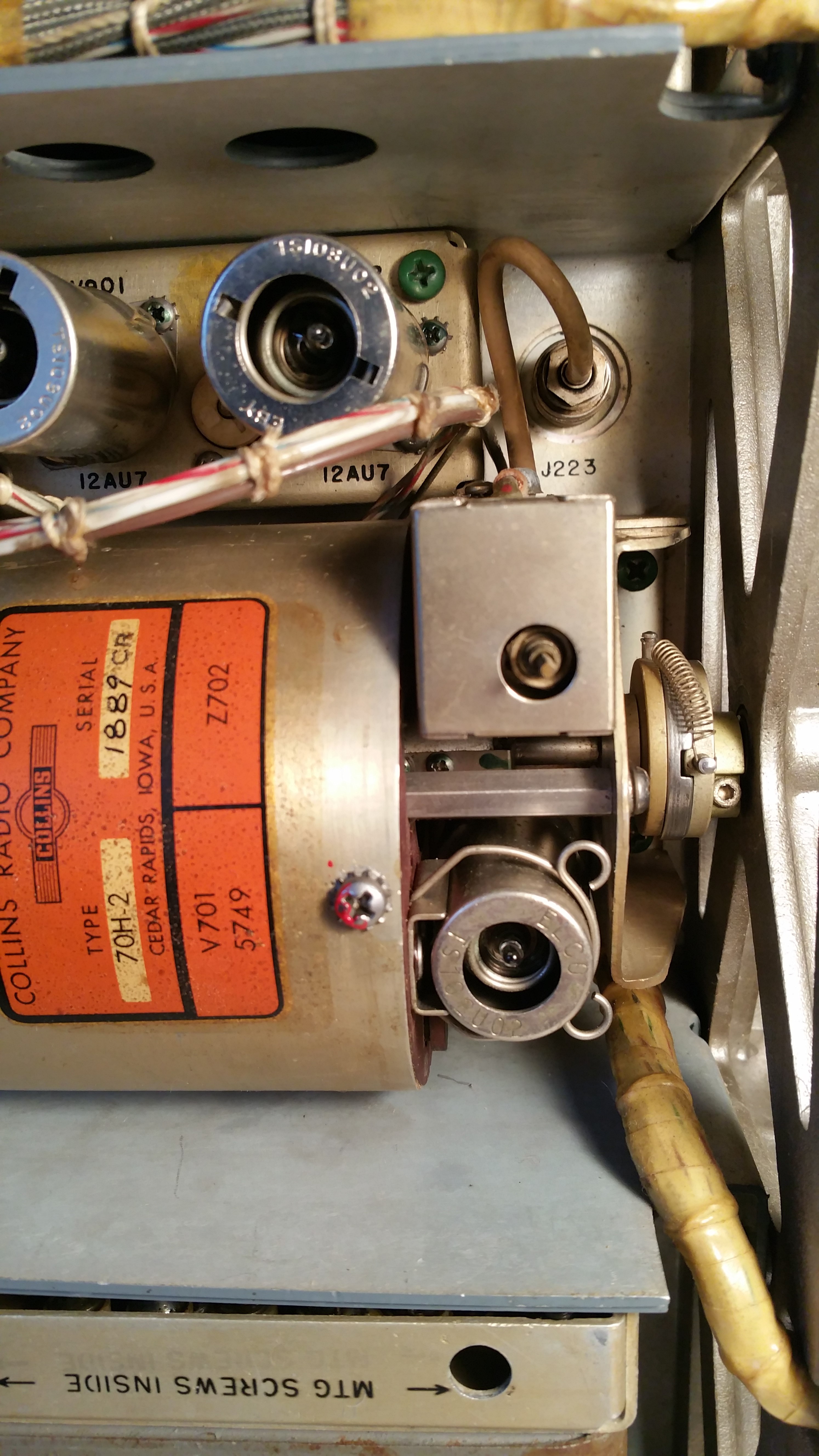
The PTO Again - April 23, 2017 The thrill of hearing a station for the first time on 1250 kc was tempered somewhat by the fact that the Kilocycle dial was reading 1490. Hoping to hear WIKE our local 1 KW station on 1490, I instead discovered that I had a 240 kc discrepancy between the PTO and the Kilocycle dial. I was pretty sure the PTO and dial would be out of sync when I roughly centered the PTO travel with the 10-turn stop 3 weeks ago. So now I have to deal with it and it's making me nervous again. Do I lift the RF Deck and reposition the geartrain to match the PTO? Do I simply adjust the dial and leave everything else alone? If I move the PTO 240kc by itself to match the dial will there still be enough travel in the PTO to go from end to end? I've read over Dave Medley's PTO Alignment Procedure a number of times and I feel pretty comfortable with it so I decided to use that and see what happens. |
|
 |
 |
I pulled P223 off its jack and plugged it into a fequency counter. The PTO should be giving you the range of frequencies from 3455 kc at 000 on the dial, to 2455 kc at +000. I set the Kilocycle dial to 000. I pulled the backlash spring off of the oldham coupler. Then I loosened the front PTO oldham coupler clamp and spun the PTO shaft until the frequency counter read 3455 kc. I tightend the clamp and spun the dial up to +000. The frequency counter read 2433.70. Let's hope we can make up that difference with the dreaded endpoint adjustment. I checked the PTO travel from top to bottom and didn't feel any resistance. And the dial readings more or less (mostly less) aligned with the received stations. So once again I've ballparked the PTO alignment. Have I just added another rookie mistake to the PTO alignment or am I close enough that I'll be able to make up those 21.30 kc with the endpoint adjustment? We'll see. I'm going to start with the IF and RF alignments now and deal with the PTO again later. |
|
Taking Stock - April 22, 2017 So, other than squeezing out a couple of BCB stations what have we really got here: - Most functions somewhat operational. - Weak to non-existent RF sensitiviity on all bands. - No CAL signal. - PTO calibration off by 240 kc. - Possible intermitent in RF path somewhere around V202. |
|
Success - April 21, 2017 At least on the BCB. Just tweaked on the RF coil cores and trimmers until something came through. No CAL signal, not sure about BREAK-IN but everything else is at least close to operational so far. |
||
 |
||
 |
||
|
Wonder when was the last time "Boogaloo Down Broadway" was playing through speakers hooked up to this radio. |
||
 |
||
|
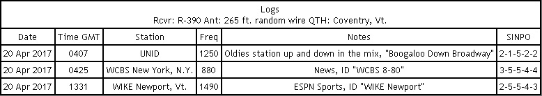
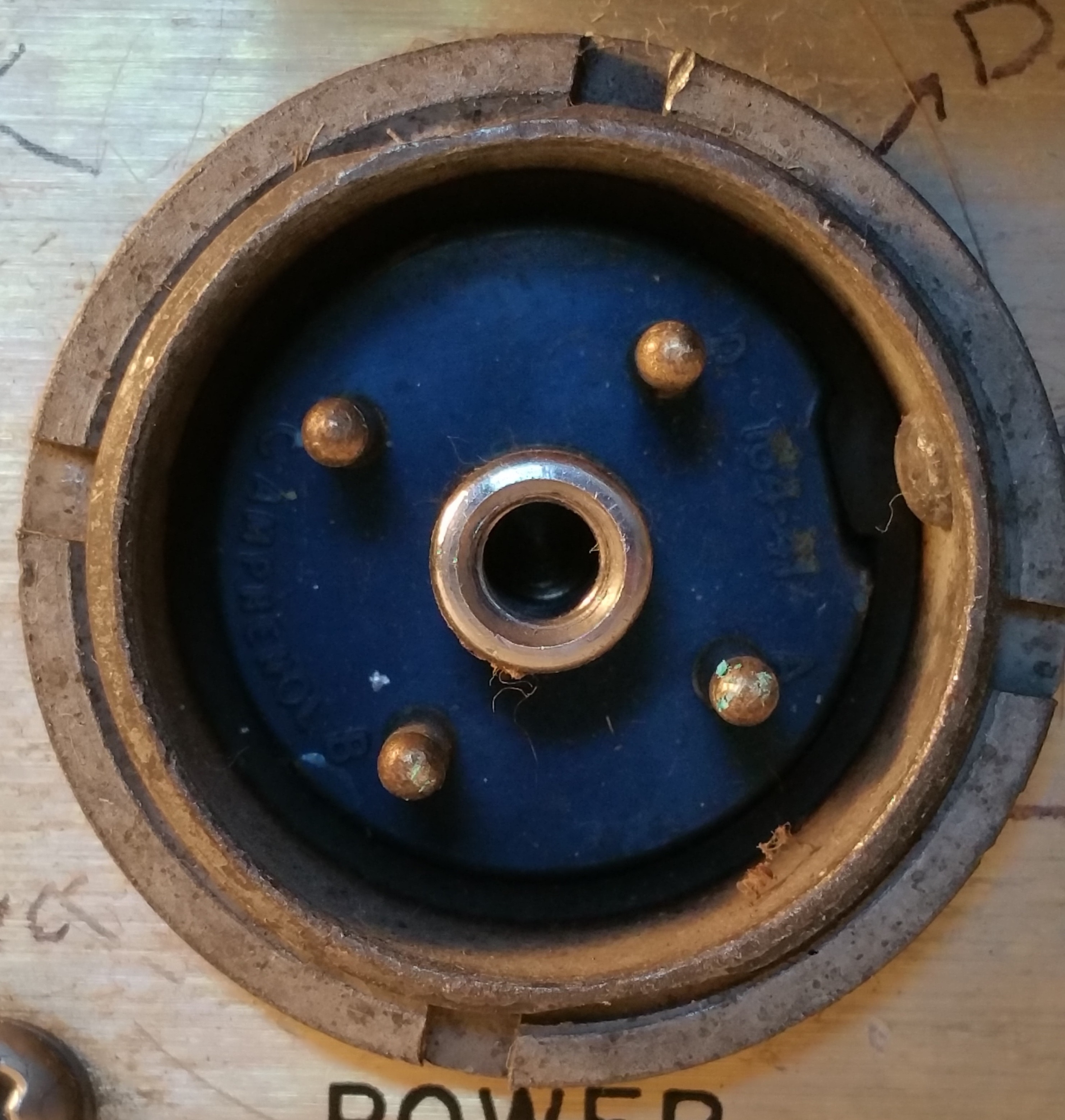
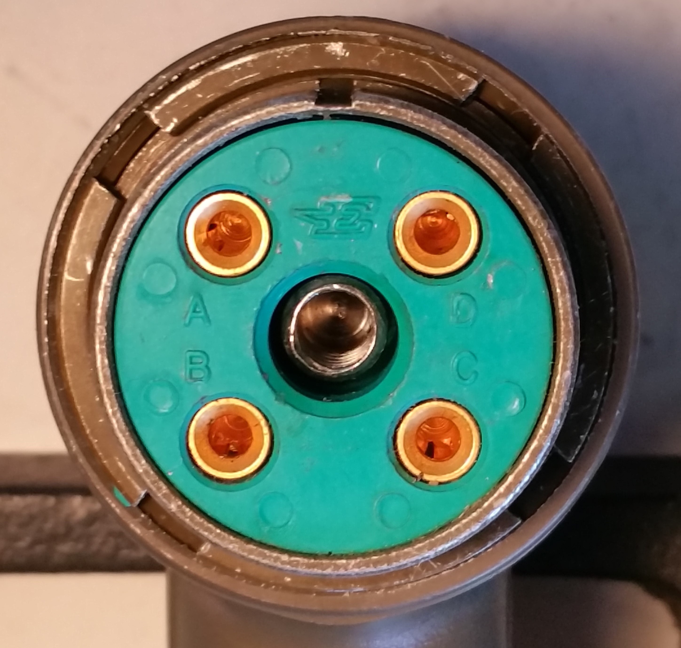
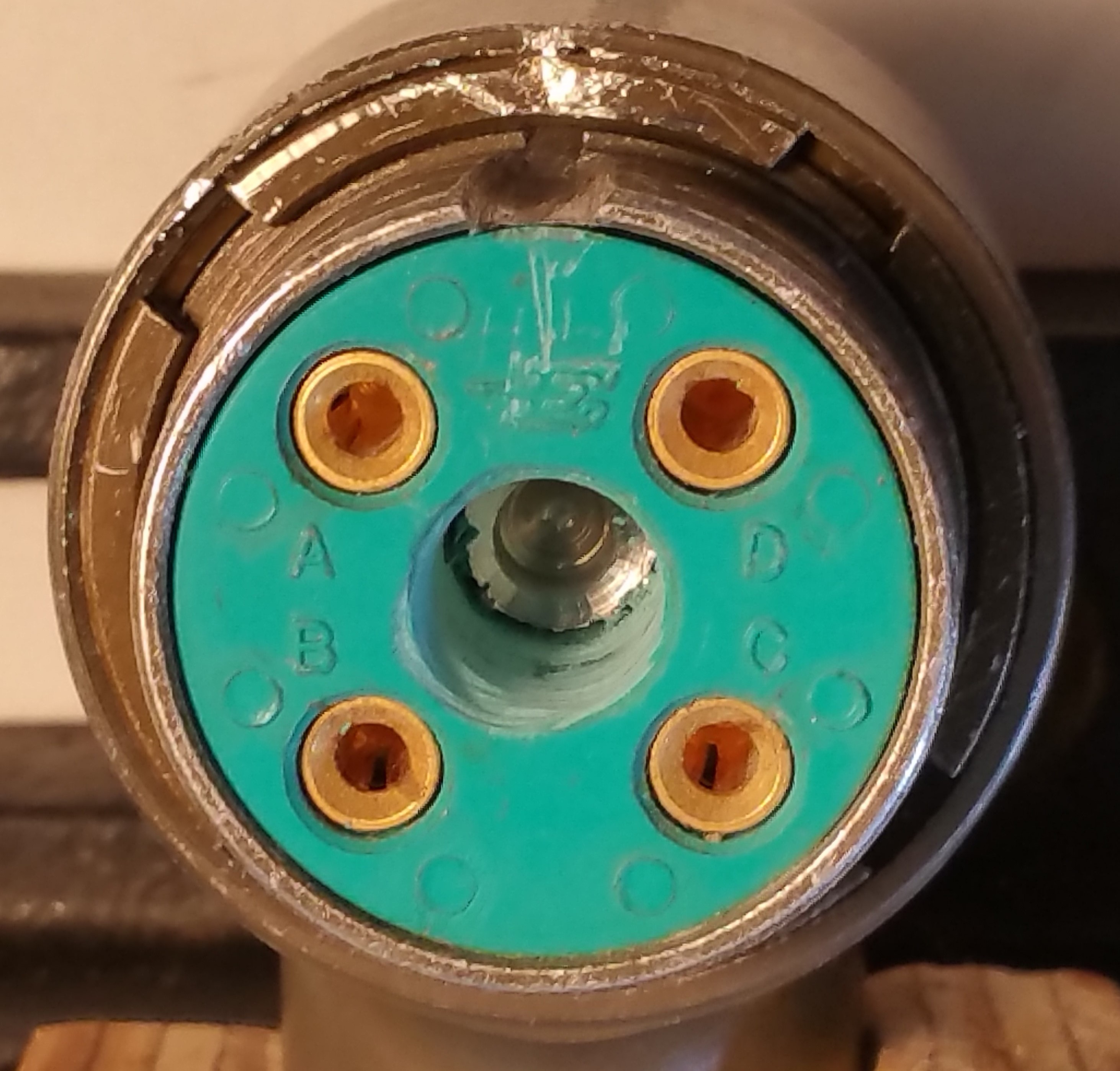
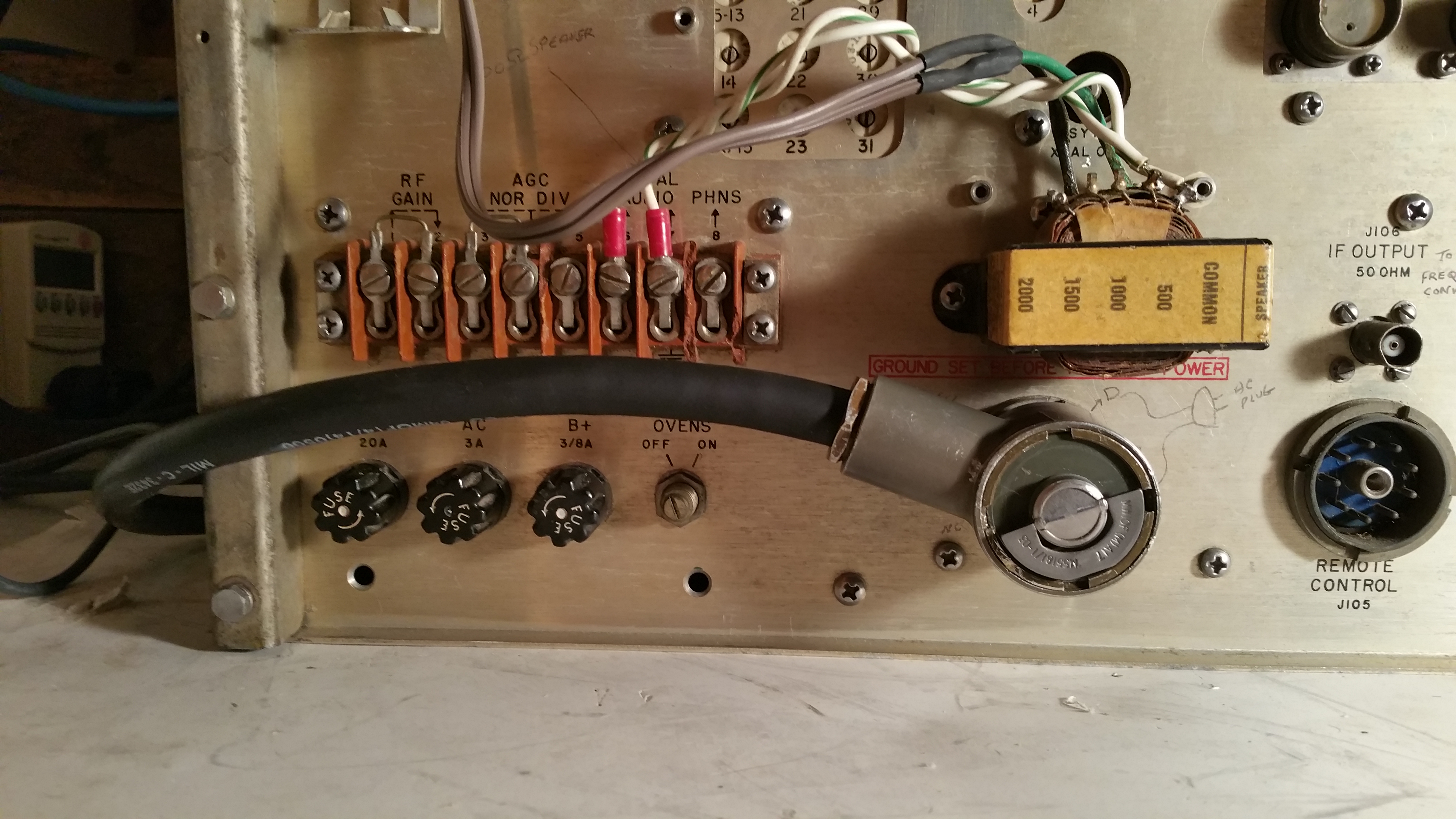
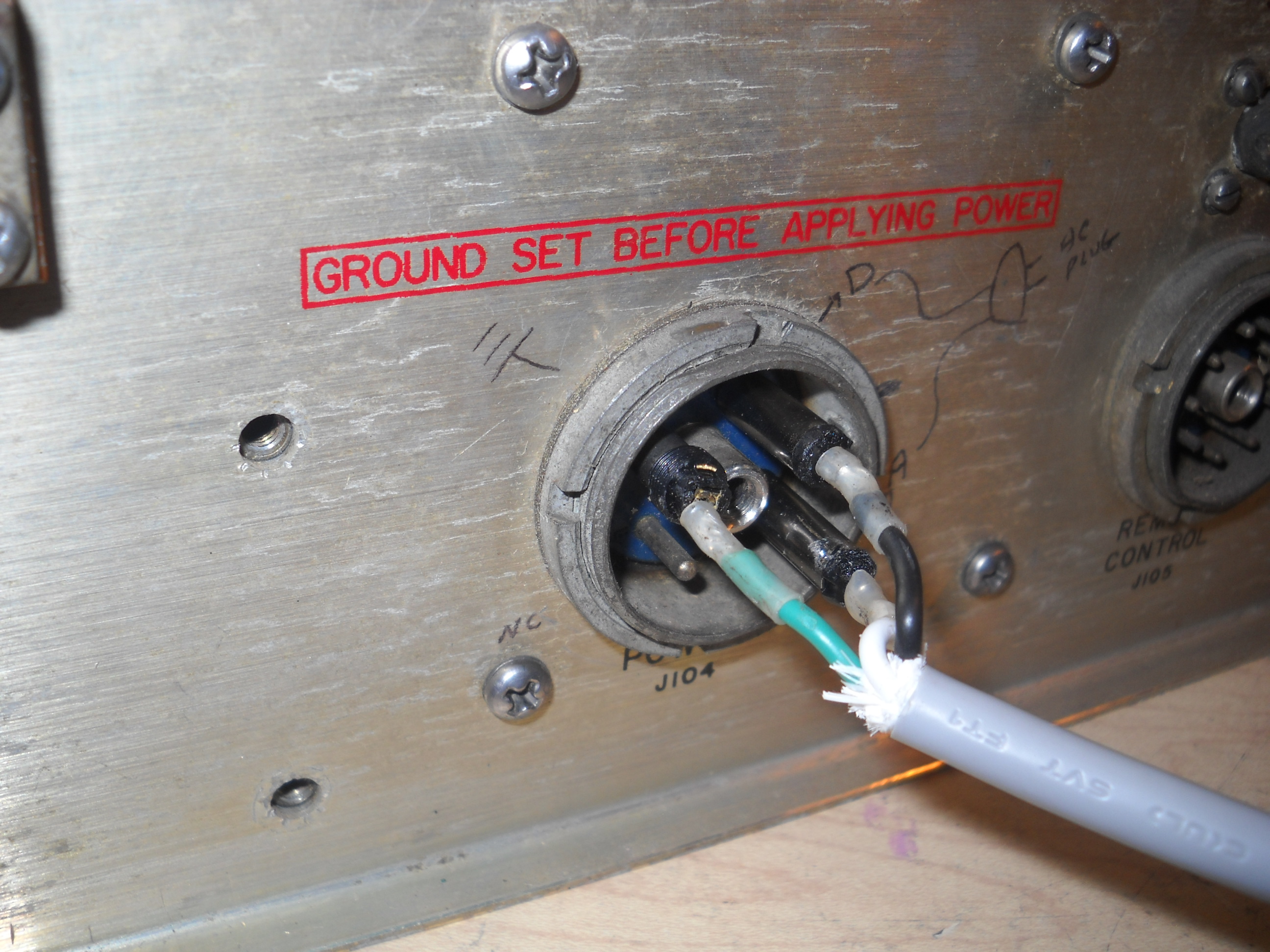
Modifying A Power Cable - April 18, 2017 Surplus Sales of Nebraska has stocked up on a faux R-390 power cable that is not quite the right fit. Nor is it wired properly for the R-390. But it's close enough that with a little bit of butchering, tugging, pulling and soldering you can get a good snug fit on a plug that will power up the radio. |
||
 |
||
|
The cable plug has a keyway that is too narrow, and an internally threaded center post that clashes with the same post on the radio connector. I widened out the plug keyway with a handfile and then drilled out the plugs center threaded post. |
||
 |
 |
 |
|
Initially I thought the cable only needed some butchering to make it fit on the back of the radio. To my disappointment it also needed re-wiring. I've never been very good with the mechanical side of this hobby. Working with metal has always been a foreign subject to me. And staring at the military connector I now needed to rewire, I assumed there was some type of obscure, expensive tool I was going to need. A specially made jig with 4 prongs that would fit into the slots in the locking rings and magically alllow me to open it up. |
||
 |
 |
 |
|
Thankfully I got some common sense advice from Don WC4G. Take a pair of needlenose pliers, stretch it across the slots and twist. Huh, who knew? I rewired the plug A=AC, C=GND, D=AC. To make everything fit back inside I had to take a hacksaw blade to the post on the twistable back cover of the shell and lop it off. Once I did that the connector closed up nicely and I tested it this morning with no problems. |
||
 |
||
|
An AN/URM-25D Detour - April 13, 2017 |
|
|
So far I've been able to get a decent 455 kc signal through the 3rd Mixer tube, and a noisy 2.8 kc signal through from the 2nd Mixer Tube. Checking AGC there's no AGC voltage showing at all so that needs to be looked at. But the AN/URM-25 is showing its age. It's time to make a detour from the R390 and dig into the signal generator. |
|
First Full Power Up - April 9, 2017 ...and it did not explode. On the Variac at 115VAC - Dial lights and top deck filaments all lit. Both 6082's glowing, red hot and measuring 179 regulated volts. No RF getting through but scratchy Local Gain audio pot heard in the speaker. I've got something to work with. |


|
|
With no Cal signal getting through I started poking around in the IF section. I found my homemade tube extender and started reaquainting myself with the AN/URM-25 signal generator which hasn't been turned on in about 20 years. The 455 kc signal was getting stopped at the 5th IF amp V505. This was the subbed 6DC6 which was good in the tube checker. I swapped it out for the one weak spare 6BJ6 I had left and the signal came through. To double check I put the 6DC6 in the tube tester again and it was good. I put it back in IF amp chain and the signal was gone. So the 6DC6 stays out of the radio for now. Something to ponder on later perhaps. |
|
|
Final Check - April 6, 2017 Everything is back in place. Checking for continuity at tube sockets for any major shorts. Nothing found, except for an apparent mistake in the TM-35 manual resistance\voltage chart. V510 pin 8 is the cathode of the AGC rectifier tube which the schematic shows tied to chassis ground. I also measured 0 ohms here but the chart says I should have been seeing 8 ohms. |
|
 |
|
|
Went through all the tubes and didn't find any of them bad. The IF Deck came equipped with a 6DC6 in the IF amp chain. My trusty old Tab Tube substitution book says they are the preferred sub for the 6BJ6 so we'll leave it in and see what happens. |
|
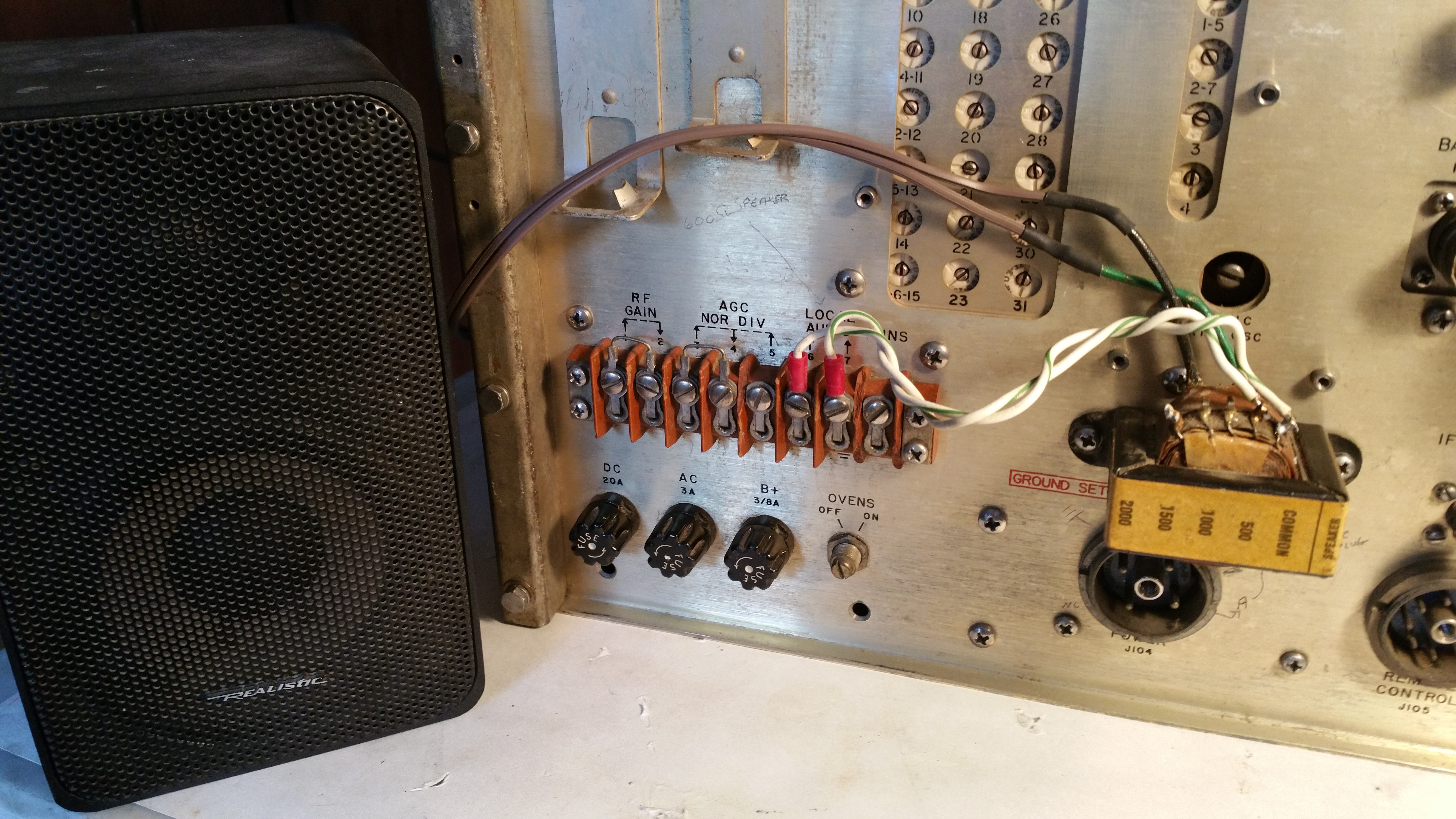 |
Getting ready to do a first real power up of the radio I forgot about the audio in the back. Rummaged through my boxes and found one of the old Bogen matching transformers I had stocked up on years ago. The mounting holes on the transformer flanges fit perfectly on the back panel above the power connector. |
|
April 5, 2017 - Reinstalling the RF Deck Putting the RF Deck back in the chassis was a bit of a chore for me. Trying to follow the TM-35 manual procedure on replacement of the RF Deck I got stuck on number 1. Couldn't get the Kilocycle Change control locking disk moved forward. If it's the first clamp on the shaft that holds it down I couldn't get it to budge. Next I got hung up on the concept of lifting one side of the deck off the chassis with a screwdriver and "loading gears by two teeth". That phrase just doesn't register with me. I'm assuming it is a procedure to prevent the RF deck gears from clashing with the chassis gears when you position the deck in place but I just couldn't wrap my head around what it meant. So I just kinda clunked the deck in place. Which is what it did, with a clunk. |
 |
And then I had to repeat the whole thing when I realized I forgot about the oldham coupler disks for the Crystal Oscillator and the PTO. Don't forget about the oldham coupler disks. I put a little grease on the oscillator coupler and stuck the disk on to it. Then I gently placed the RF deck in place and got the couplers lined up. I flipped the radio over, removed the PTO and somehow was able to reinsert it with its coupler disk intact and lined up with the RF Deck. And after 2 years I even managed not to lose the Oldham coupler loading spring (although I kept it in a small metal box not an envelope) which I dutifully stretched across the appropriate pins. |


|
With everything finally back in place, I rotated through the Megacycle dial. The action was easy but not quite as smooth as I was expecting. I could "feel" the gearing as I moved from band to band. Not bad I think, just a different feel compared to my R-390A. It is synched with the Crystal Oscillator so I'm happy with it for now. The Kilocycle control was smooth and easy but something was off with it. When I first pulled the radio apart almost 2 years ago I didn't bother to notice what frequency the dial had been left at. I kind of remember that the Crystal Oscillator band switch indicator was showing 14 but I have no idea where the Kilocycle dial was sitting. I'm assuming that wherever it was, that is where the PTO is now sitting. Kind of anticipating that there is some type of realignment I will have to do with the PTO I put the Kilocycle dial in the middle at 500 before reinstalling the RF Deck, hoping to split some kind of difference, somehow. When I went through the rotation of the Kilocycle dial everything seemed fine going up past +000, but reversing and moving down I could feel some resistance starting around 200. Assuming that I was approaching the end of the PTO travel I loosened the PTO coupling clamp and moved the dial down to -972 and then tightend the clamp back up. I was then able to rotate the dial all the way through both ends. In my novice brain I am telling myself that I have kind of roughly synched the PTO with the RF Deck. Either that or I've made some big rookie mistake that I will pay for later. Let's see what happens. |
|
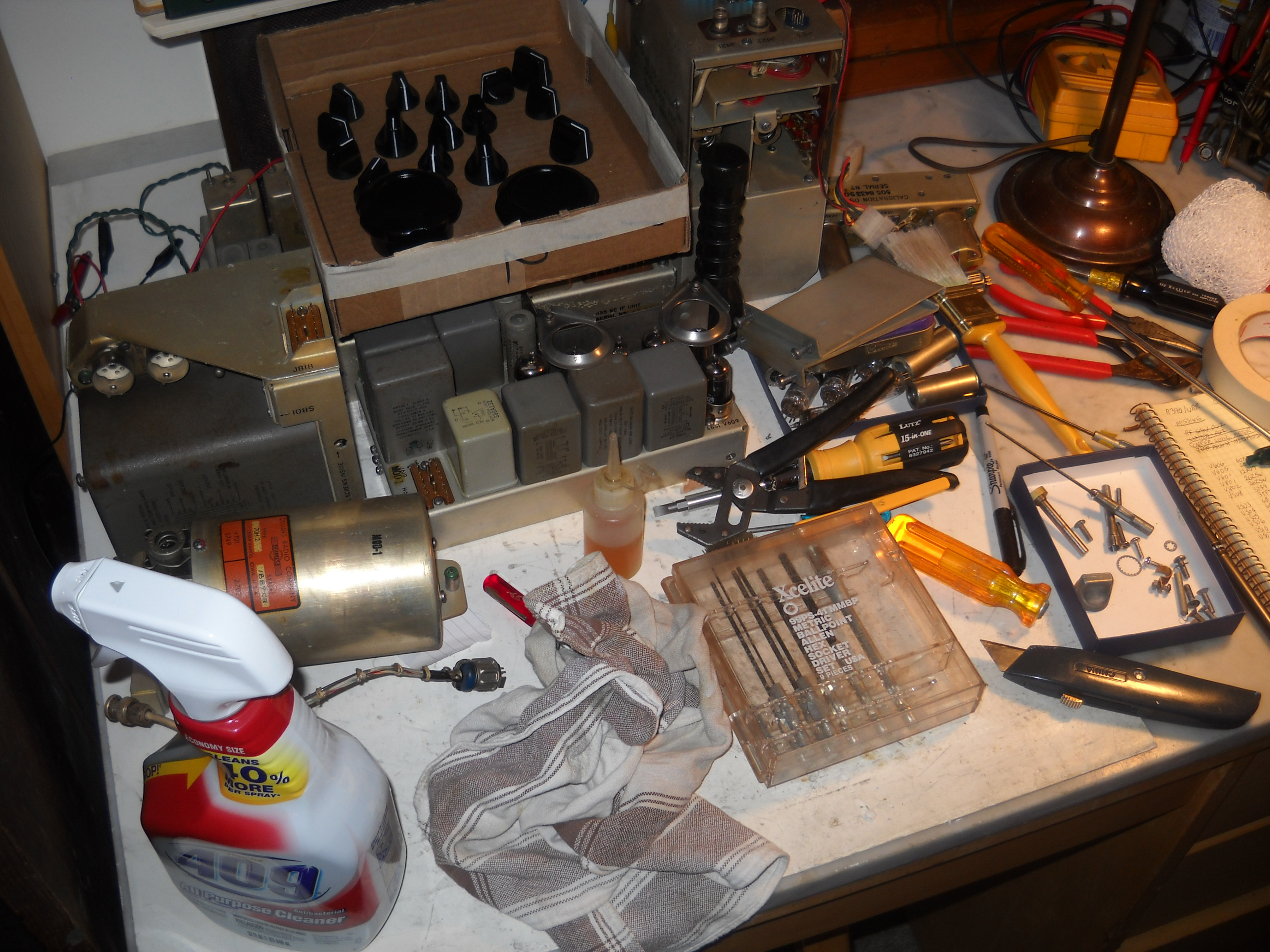
April 4, 2017 - Loose Ends The RF deck is done. Ready to go back in the main chassis. Just a few more loose ends to take care of. Cleaned old grease out of the Crystal Oscillator wormgear. Found proper brass hardware and spade lugs for Carrier Meter. Pulled an R-390A RF Gain pot and installed it on the front panel. |
|
 |
|
Replaced the selenium rectifier in the Power Supply with a good old fashioned Radio Shack full wave bridge rectifier (#276-1173) |
|
 |
 |
|
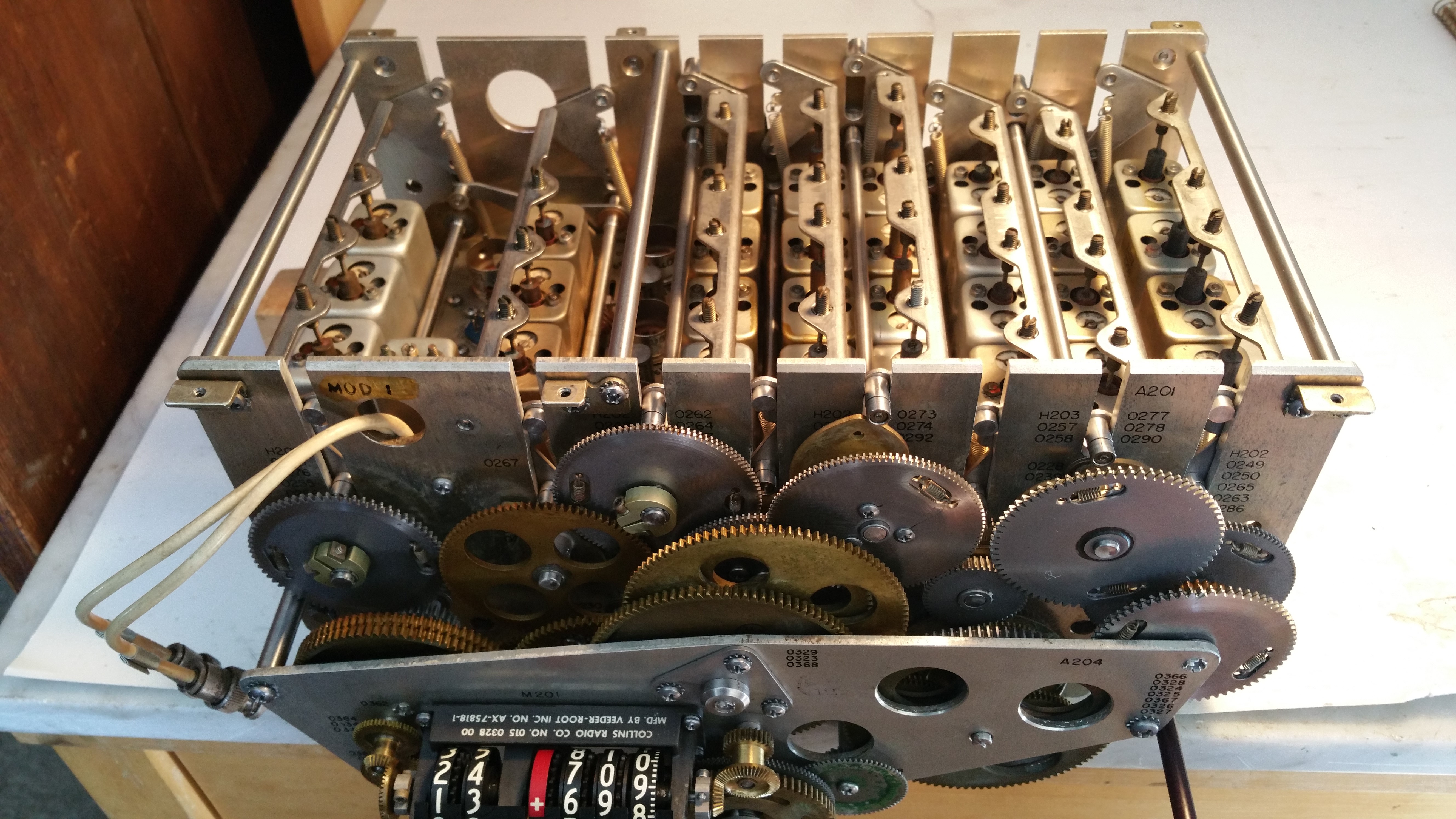
March 31, 2017 - The RF Slug Racks All the RF coil cans are back in place. Going through the slug racks, cleaning and oiling. You can see the 4-8 Mcs rack has one slug that was resoldered previously and it's a bit off-center and wobbly. The replacement 1st IF rack was extremely corroded around the set screws. They wouldn't budge until I worked some machine oil down into the threads. |
 |
|
March 25, 2017 - The RF Coil Cans The RF deck is cleaned, oiled and mechanically aligned. Inspecting, cleaning, repairing and replacing coil cans. 70% rubbing alcohol and a cotton swab to clean the tops of the cans and the trimmer cap. Another swab to clean out the inside of the coil tube. Deoxit on each pin connector. A drop of machine oil on the screw threads. Two of the cans have had missing spring connectors. One was laying on the deck, one came out as I was removing the can. A little cleaning of the pin and a dab of solder on the tip of the spring connector where the pin point sticks out held it in place. |


|
The coil assembly in Z212 has a slight problem. The coil tube is not aligned vertically and the bottom is off center from the hole in the assembly base. Whoever put the huge glob of glue at the bottom to hold the coil in place missed the mark. Maybe not a big deal with the flexible springed coil slugs, but I'd rather have less drag from the slugs than more. I've got a good spare Motorola can. |

|
|
March 19, 2017 - Mechanical Alignment As an R-390 novice, most of my experience consists of reading other peoples accounts of their adventures with this radio. From my reading so far, there are two areas that scare me to death. Number one is the PTO alignment and the dreaded endpoint adjustment. Next in line has been the looming mechanical alignment of the RF deck cams. There's the mysterious "green wheel" that is required to maintain sync when you remove the RF deck from the main chassis. And the warnings of hidden disassembly traps that will instantly mess up the mechanical sync and that recovering from a loss of synchronization is a major and time consuming chore. |


|
|
It now seems to me that all this angst about cam alignment is a bit overblown. A missing or misplaced "green wheel" is not the end of the world. Its only function is to keep the Kilocycle dial in sync with the cams. Unless you have a gear clamp that is loose or broken allowing the gear to spin without also moving the camshaft, the Megacycle dial and all 8 camshafts will always be in alignment with each other. Again, assuming that none of the gear clamps has ever been loose, with the RF Deck on the bench without a "green wheel" and the Megacycle dial set to 02, there will always be one position of the geartrain where all the cams will line up with the alignment marks. |


|
|
In my case I did have one problem gear clamp. The clamp on the 2nd IF camshaft was loose and the cams were way out of position. So much so that the roller for the 1st IF can rack was on the wrong side of the cam, preventing the cam from rotating. I loosened the clamp all the way, set the Megacycle dial to 02 and the Kilocycle dial to 000. I moved the geartrain around until I found the spot where the other 7 cams all lined up. In fact there was a slight "clunk" feeling when I hit that spot, as if there was some kind of detent somewhere in the geartrain. I rotated the 2nd IF camshaft to its alignment spot and tightened the gear clamp with a new screw. I put the "green wheel" back in its sync position. The geartrain, cams and dial were now all aligned. |
|
March 17, 2017 - Digging In To The RF Subassembly A return to the RF Subassembly. Pulling the RF coil cans and cleaning the deck. One transformer can missing a lock down screw. It was lodged up against the coil inside the can. An interesting puzzle to remove the screw and then drop it back into the threaded hole from outside the coil assembly. Found a single broken contact spring connector laying on the deck. I guess someone has been in here before. Underneath the 50uF C231 is bad. All the other Vitamin Q's check out OK. We'll take our chances that they hold up with voltage on them. |


|
|
Flushing out the RF Decks. A full can of WD40 on the gears, rinse the whole thing with half a bottle of 409, spray it with water from the garden hose (that felt so wrong) and then douse it with a gallon of distilled water. They're back inside now drying off and getting ready for some fine cleaning with bristle brush and cotton swabs. |
|
March 8, 2017 - Parts Found It took me a year and a half but I finally scored the parts to continue on with the rebuild. A junker radio with no IF Deck showed up on eBay. Saving on shipping costs I spent a pleasant Saturday morning driving through upstate New York to pick it up. |

|
|
September 20, 2015 - Bad News Moving along with quick checks of the Calibrator Oscillator, Crystal Oscillator and PTO found all good tubes. But then the bad news. The RF deck is missing an RF slug rack and IF can Z219. I don't know why I didn't check the deck carefully before I got all excited about this rebuild. Probably I was starstruck and blinded by the Collins nameplate on the front panel. |


|
|
September 19, 2015 - First Partial Power Up |

|
|
I'm not ready yet to spend $25 on a proper power connector, so I scrounged through the parts box and built this sketchy "slip-on" connector to start testing the power supply. I put in two 26Z5's and subbed a temporary 1/4A fuse for the 3/8A B+ fuse which I didn't have. I plugged it in and got +416 unregulated VDC at C101. A good start. Next to test would be the voltage regulator circuit. It runs through the power supply, IF and Audio decks so I did a quick check on these units. |

|
|
In the Audio deck the two 6082's were missing and I had none on hand so the order went out to thetubestore. The tube compartment was pretty scorched around the sockets but the wiring underneath looked ok. R625 and 626 below V609 the voltage reference tube were way high so they were replaced. The IF deck had a complete set of good tubes. R537 the Carrier Meter Adjust pot was broken and replaced but no other bad components were found. I re-mounted the 3 subchassis back in the main chassis, hooked them up, flipped the switch and stood back. No sparks, scary noises or smoke. A solid reading at the 180VDC regulated voltage test point, and I could hear the Squelch relay kick in when I massaged the Function switch. And for the first time in who knows how long the dial lights are glowing again. So far so good. |

|
|
September 4, 2015 - Pulling It Apart The R-390 is pulled apart. All the subchassis are out on the bench. Next the front and back panels are disconnected from the main chassis. Taking an inventory of what's missing. |

|
| MISSING SO FAR |
| Carrier Level Meter |
| Zero Adjust Assembly |
| R124 Limiter Pot |
| R123 RF Gain Pot |
| CX-1358 Power Cable |
| B+ fuse |
| Some tubes |

|
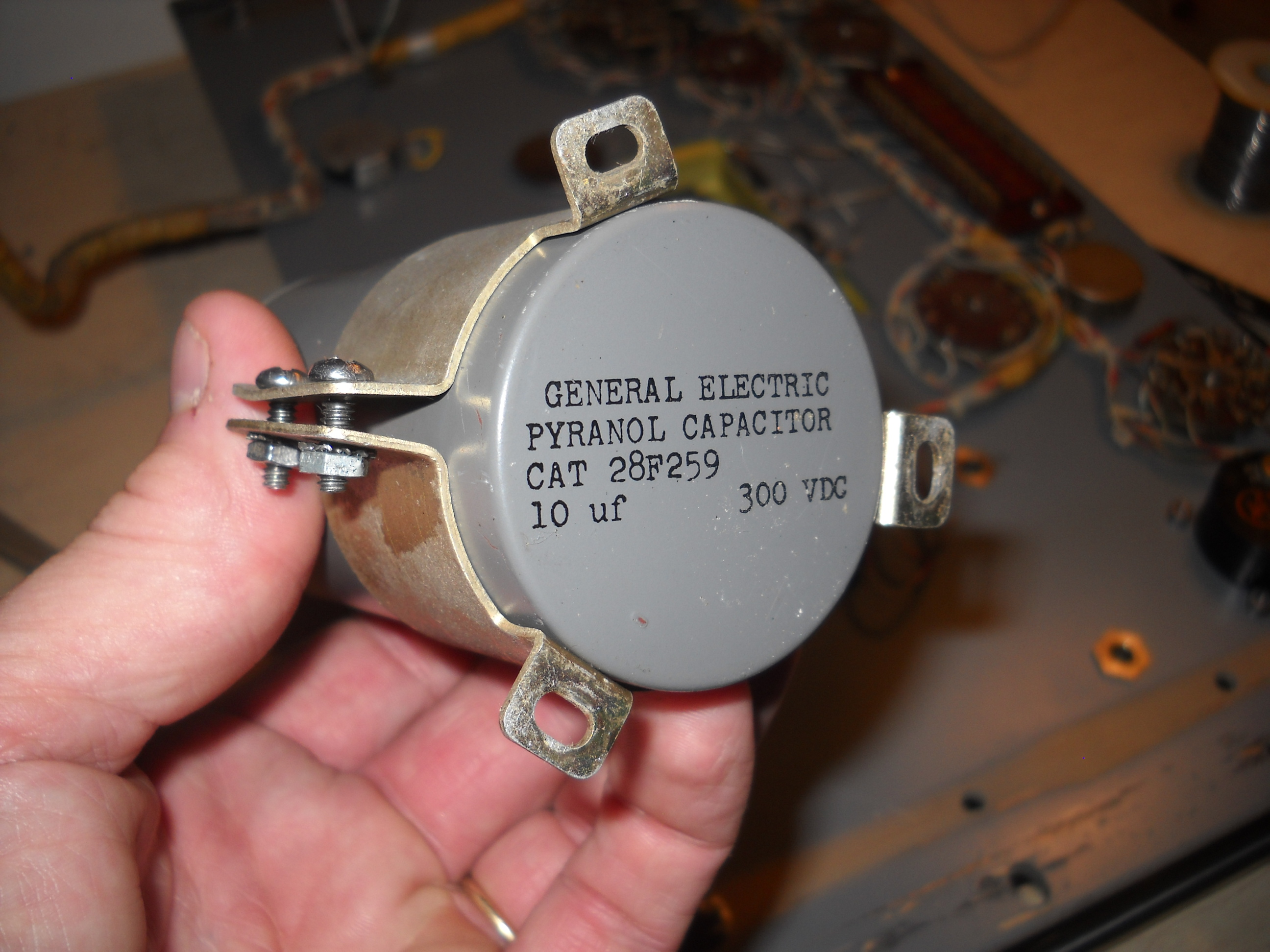
Cleaned the main chassis and panels with 409. Look at the nice and shiny pyranol capacitor. Sanded and repainted the knobs. Stole a Limiter pot from a junk R-390A frame and found a temporary 7K pot for the RF Gain. |
 2017 WA2FXM - Mark Mohrmann 2017 WA2FXM - Mark Mohrmann |
 |