| Grebe Synchrophase 7 |
|---|
|
|
| Alas, It's The Pot Metal | |
|---|---|
|
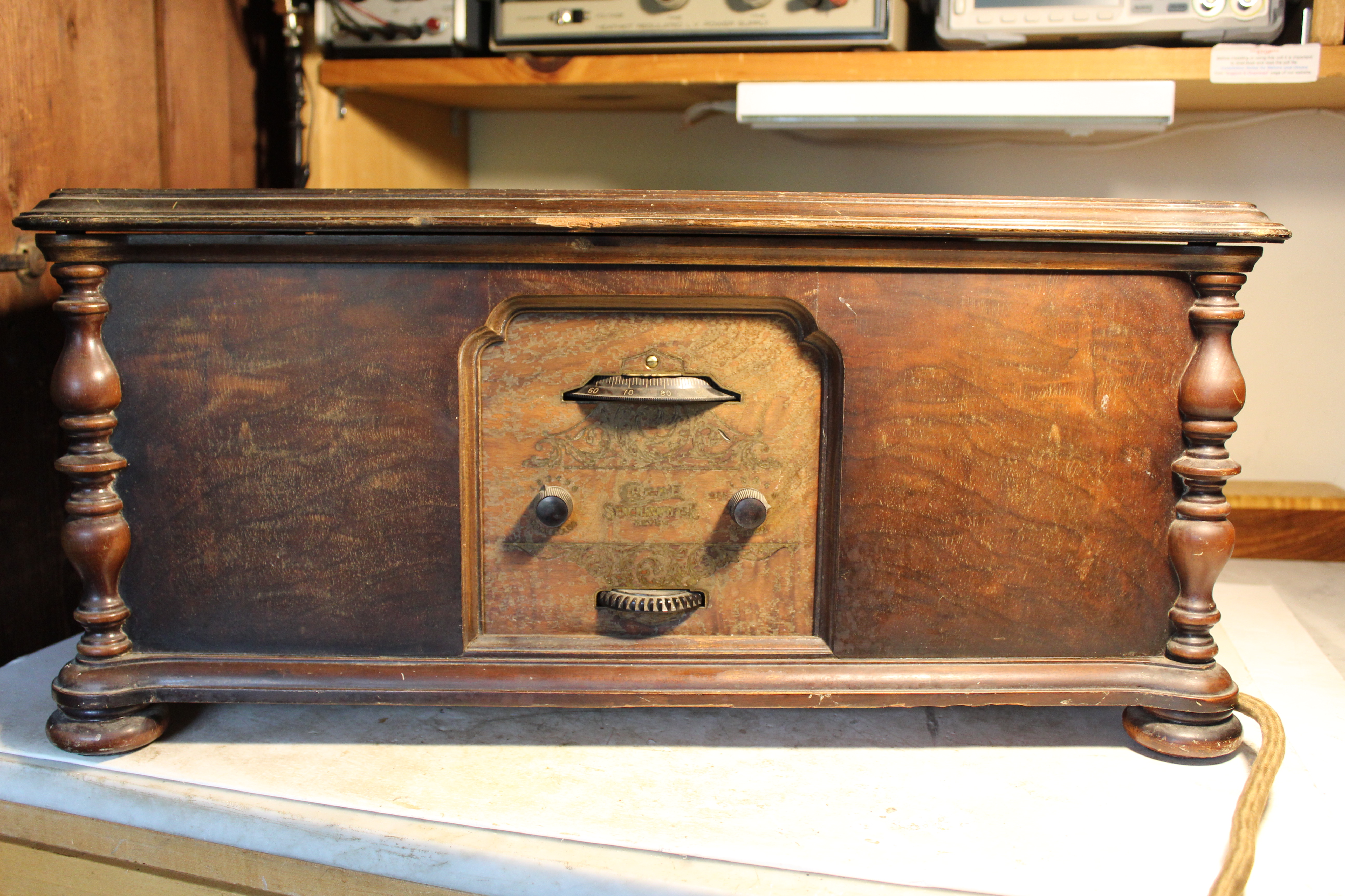
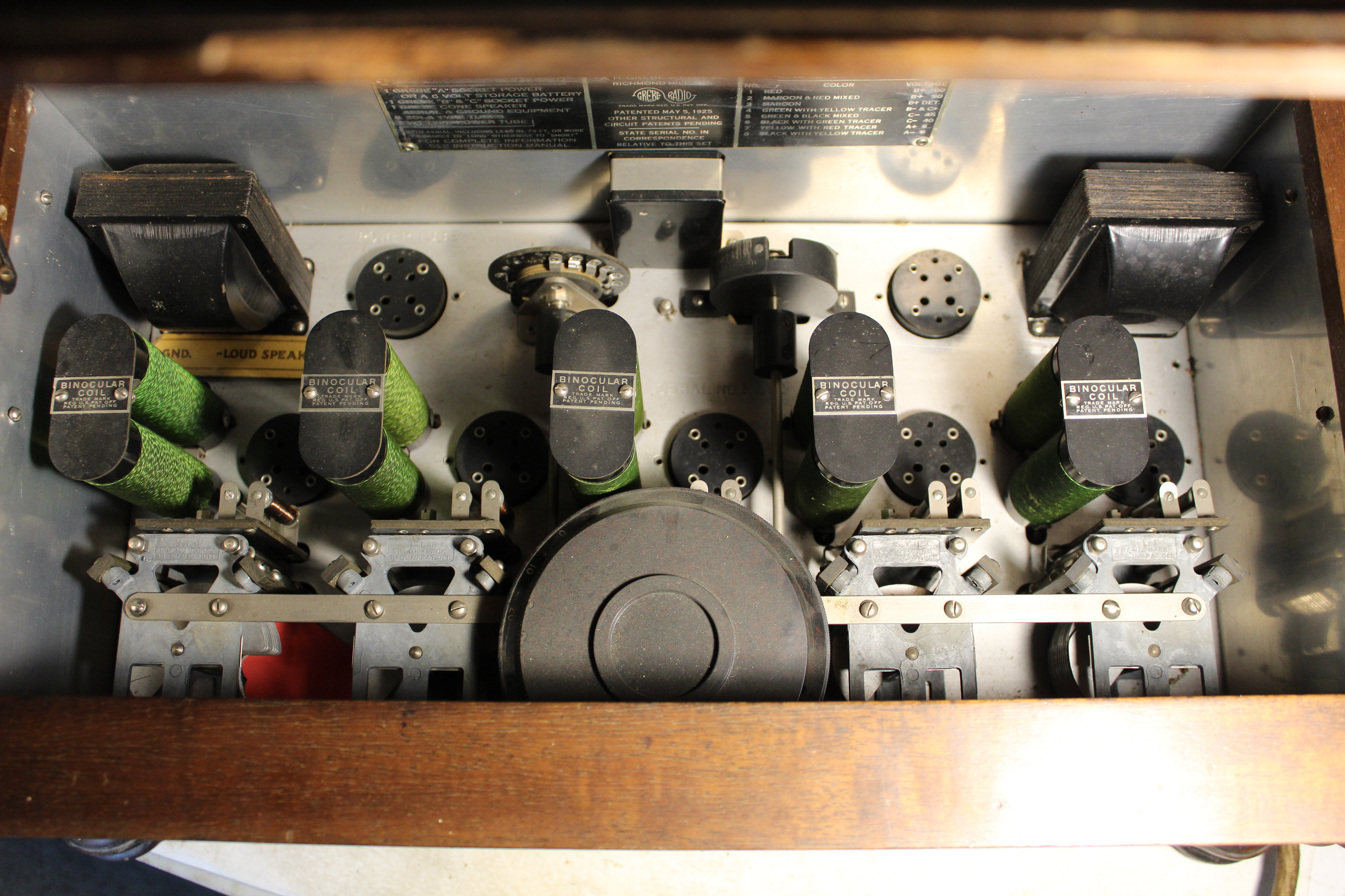
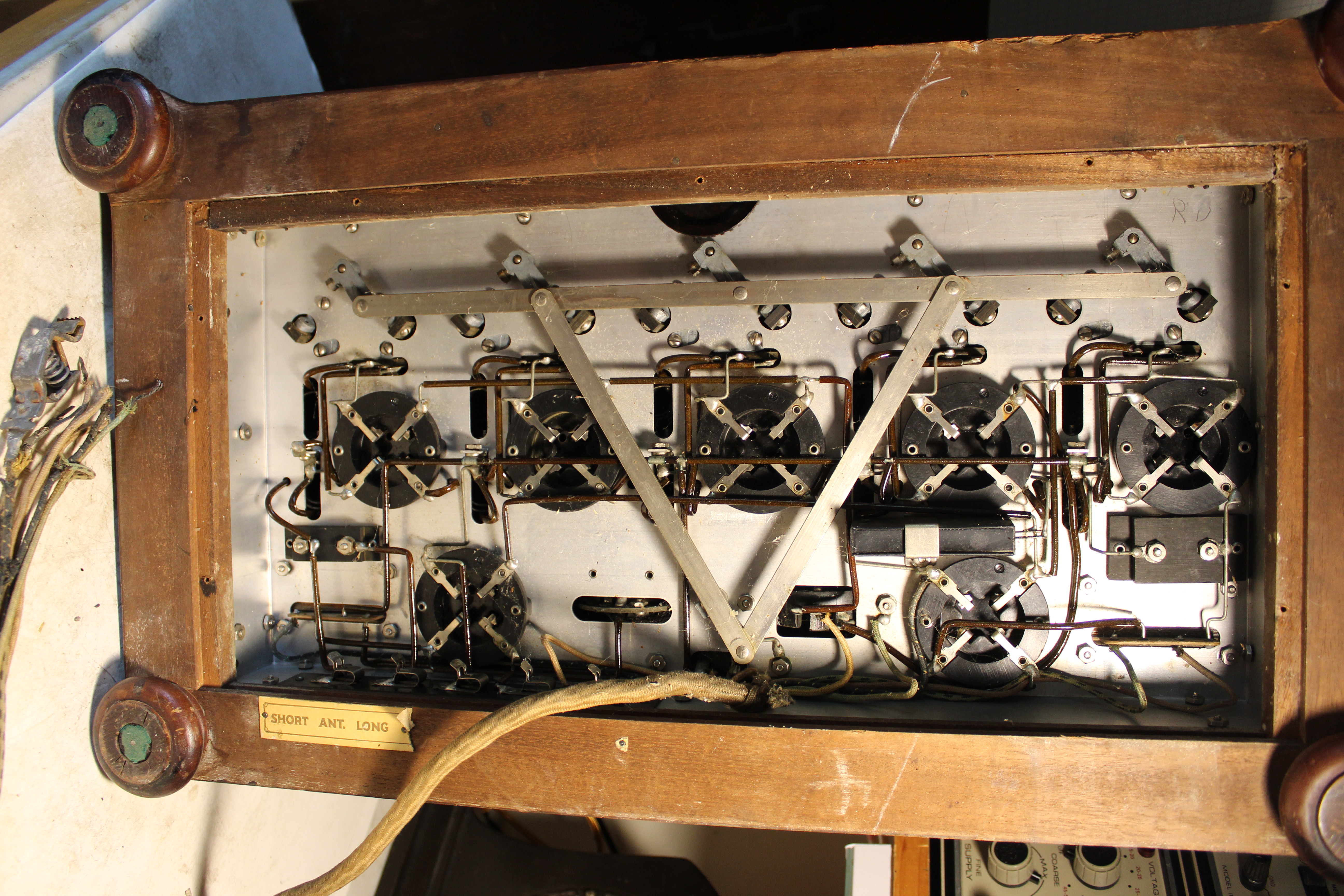
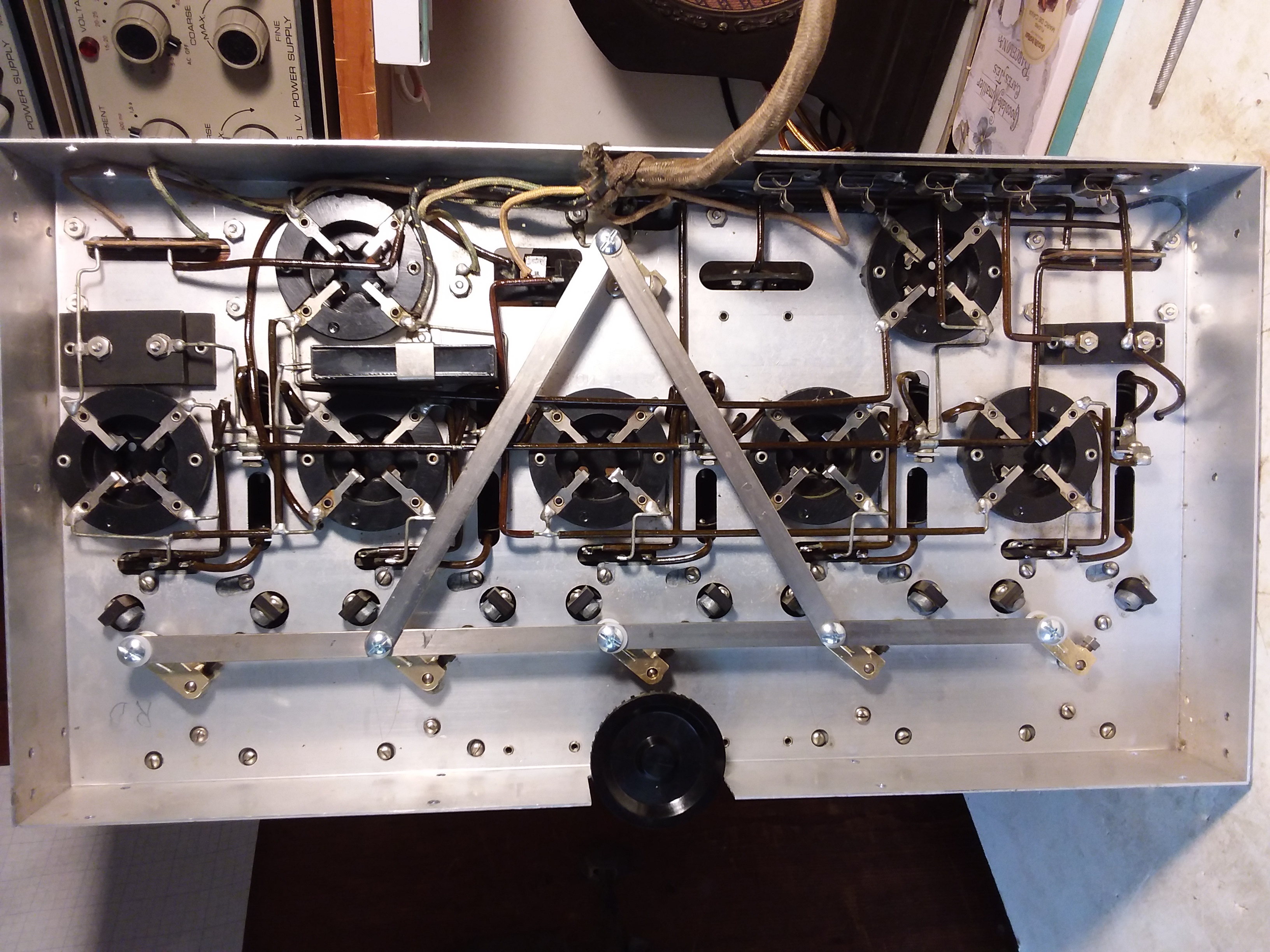
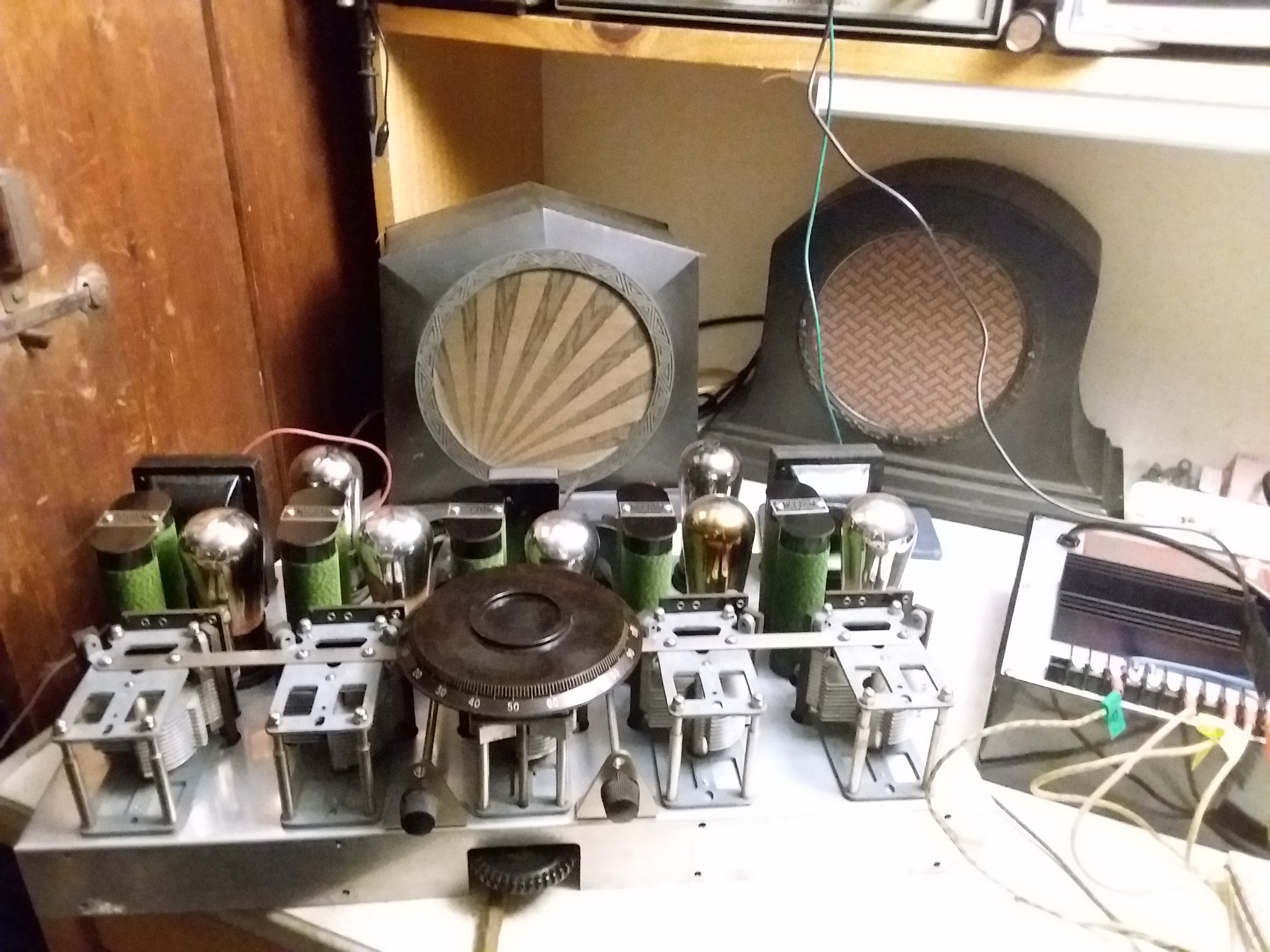
I was looking forward to working on this one. A beautiful Grebe Synchrophase 7. Especially beautiful on the inside |
|
|
|
|
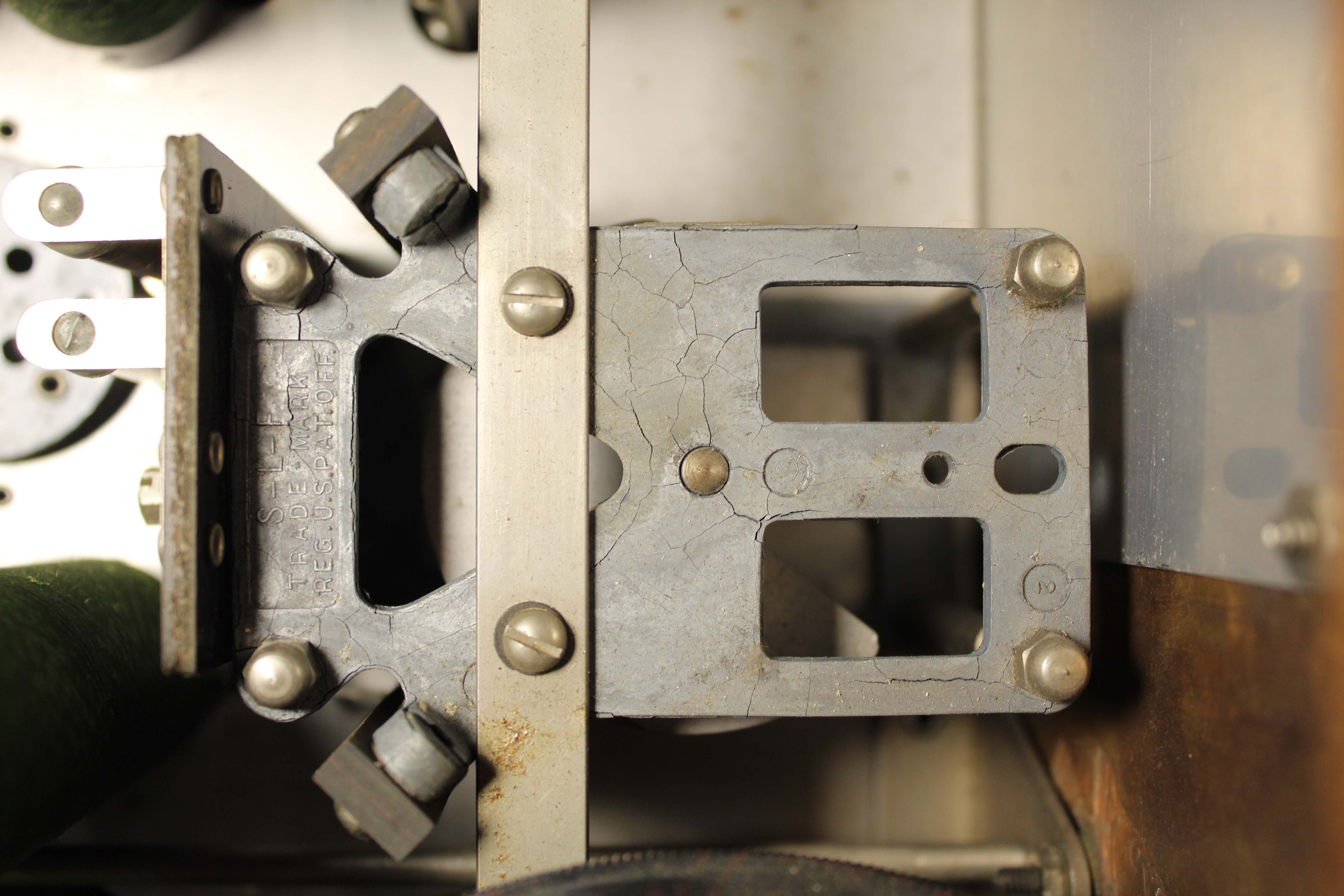
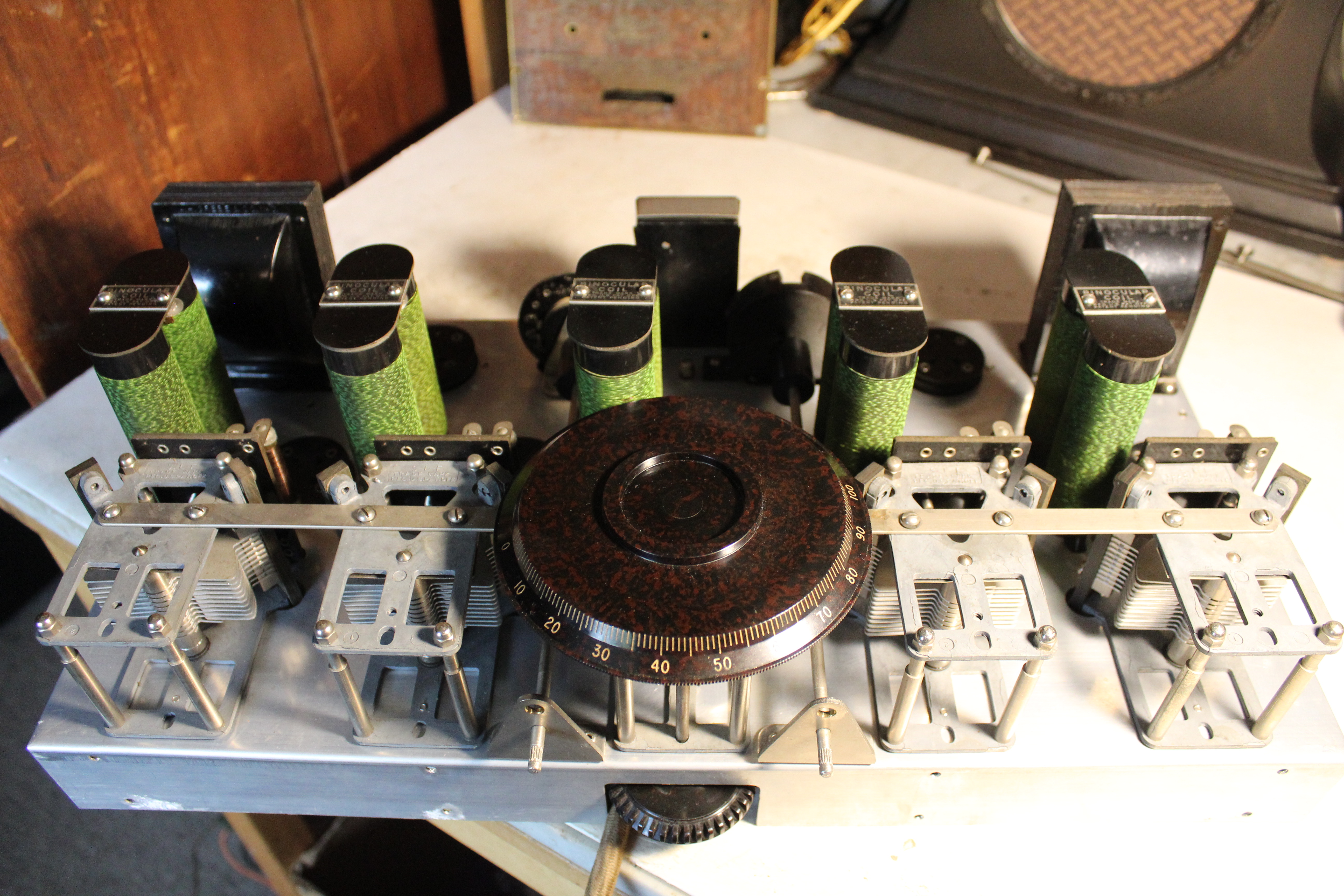
But the pot metal. The first time I ever dealt with pot metal was on an Atwater Kent. The tuning disks literally crumbled in my hands as I tried to pull them off the shafts. So what we have here in the Grebe is tuning condensers with cracked frames. Maybe not a problem. |
|
|
|
|
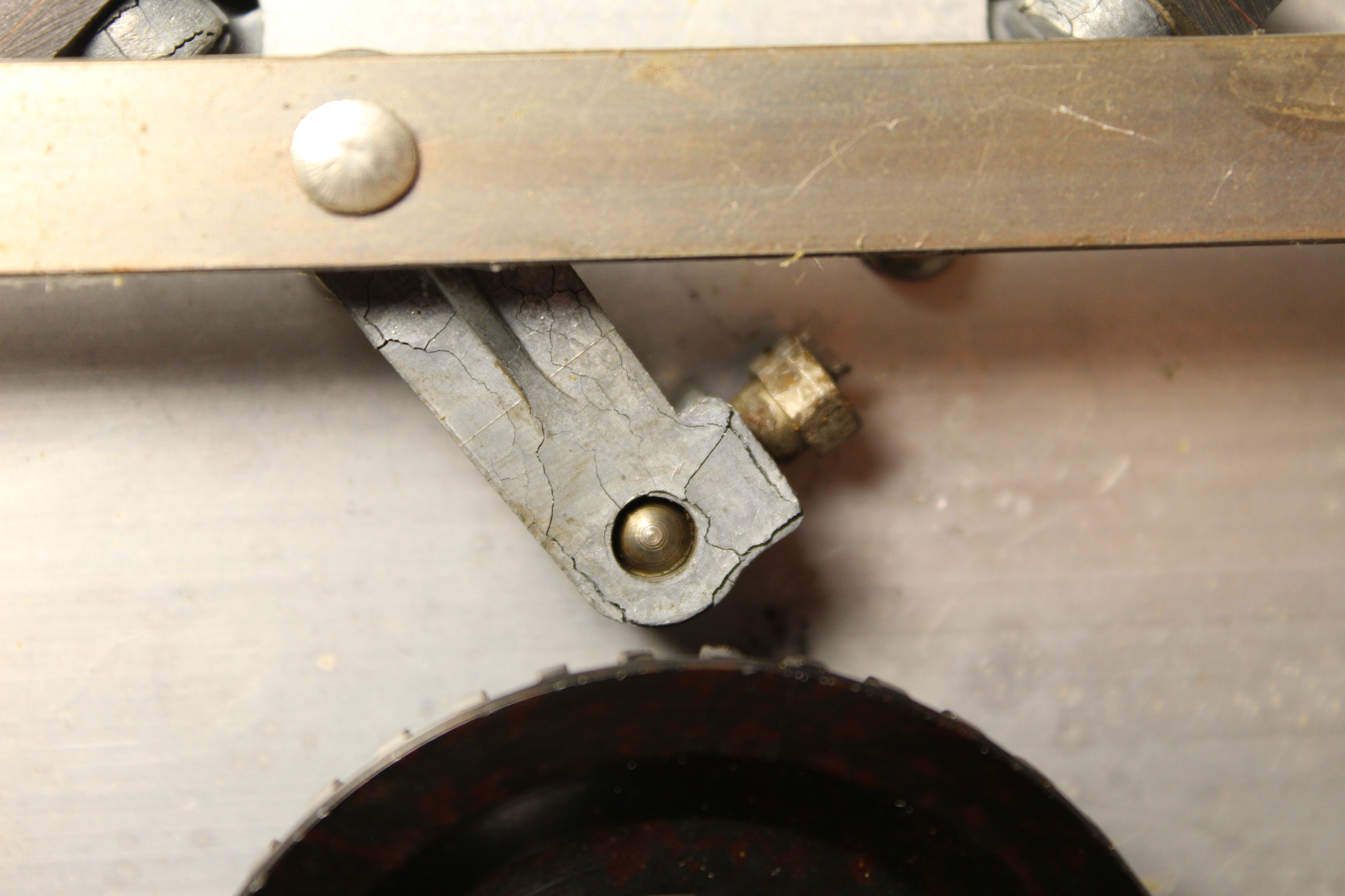
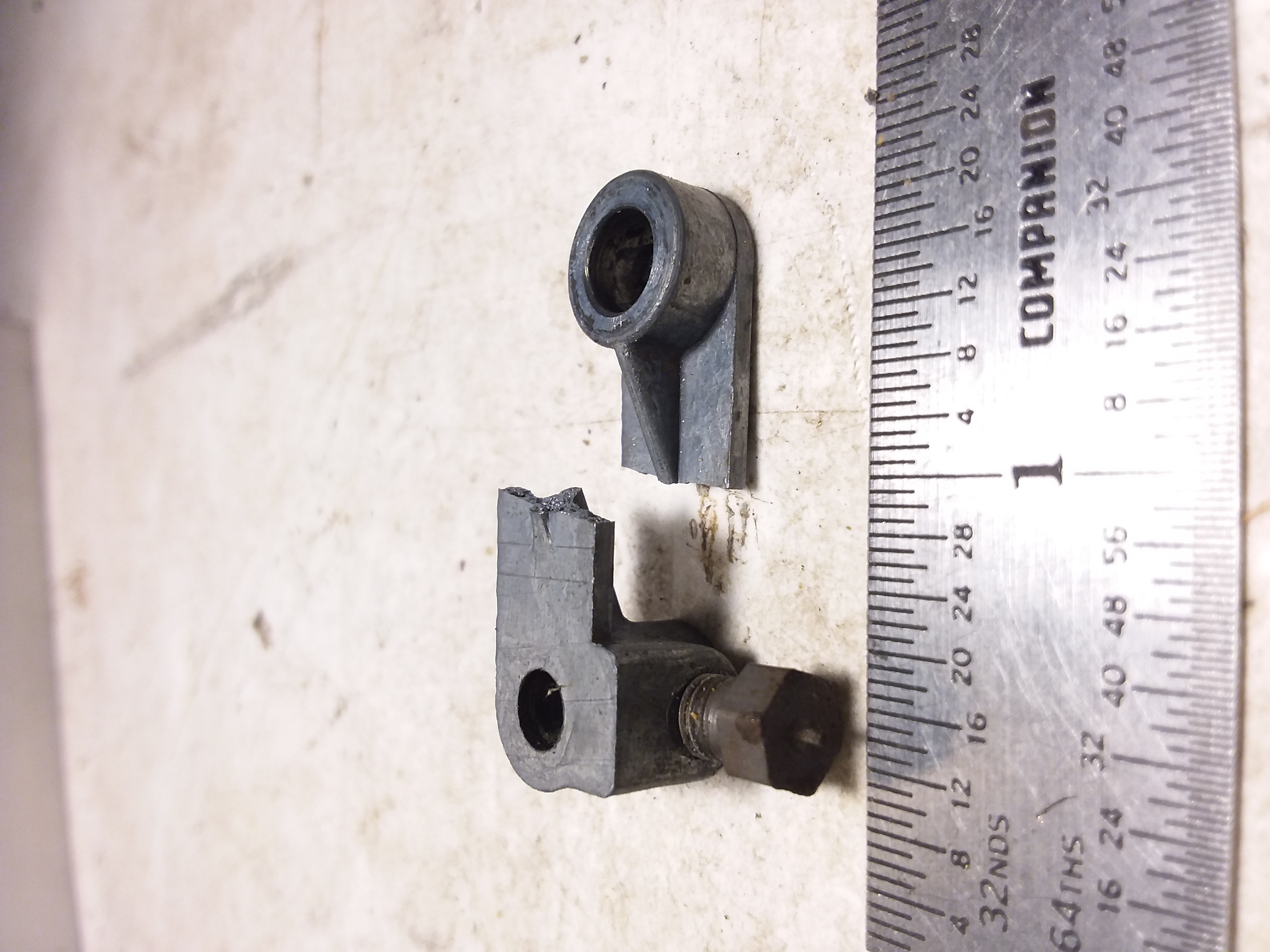
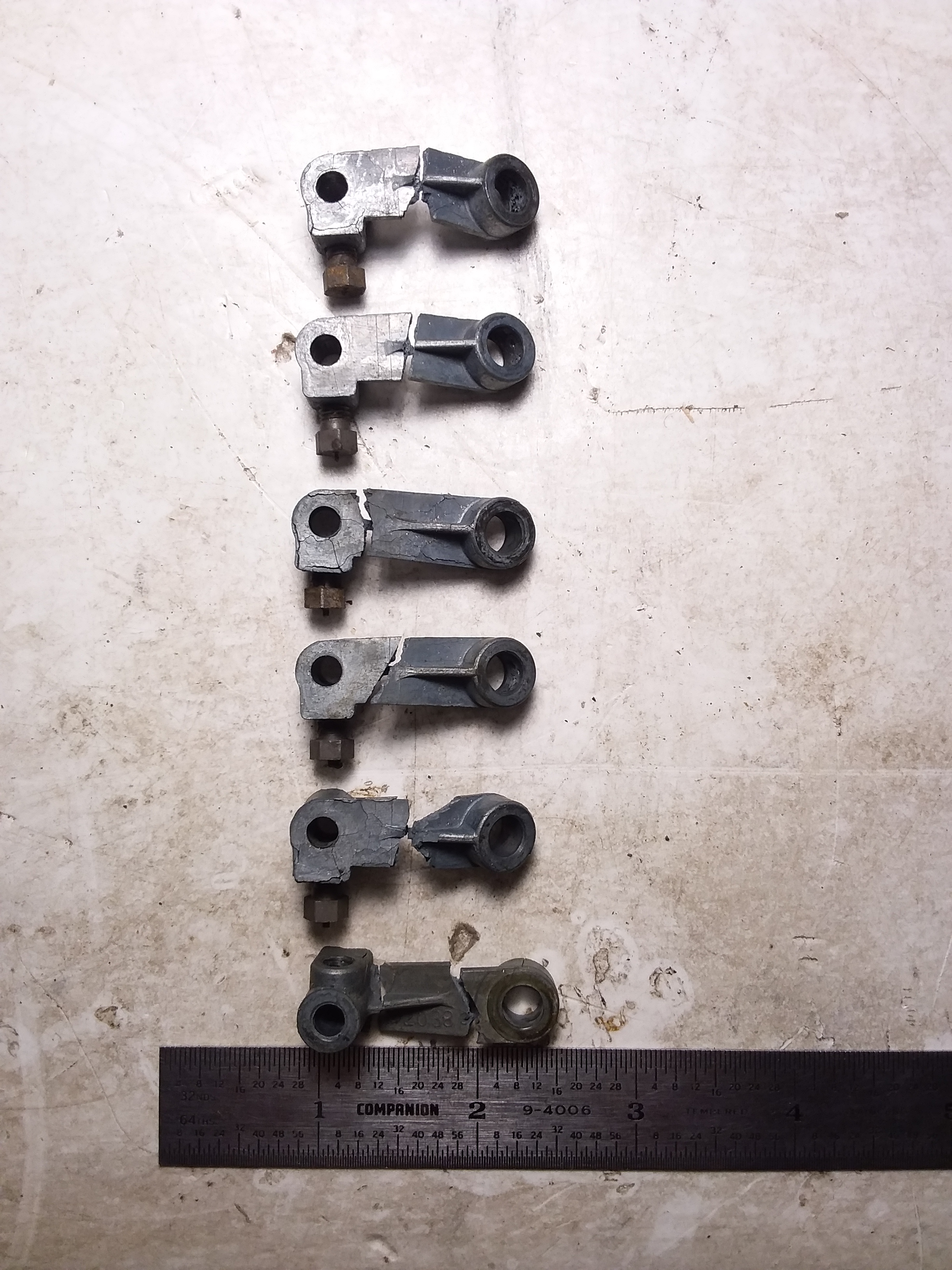
But these are the killers. The six tuning linkage pieces. One knob to turn 5 variable condensers. The knob linked to the others over a metal rod with these riveted linkage pieces. The rod was stuck tight and would need removal and lubing. All the pot metal linkages fell apart as I tried to carefully, gingerly remove the linkage rod. |
|
|
|
|
I've called one small metal fabricator to see if they would have any interest in fashioning replacement pieces. I haven't heard back from them yet. So this radio goes on hold for awhile. |
|
| Brass Castings Found | |
|---|---|
|
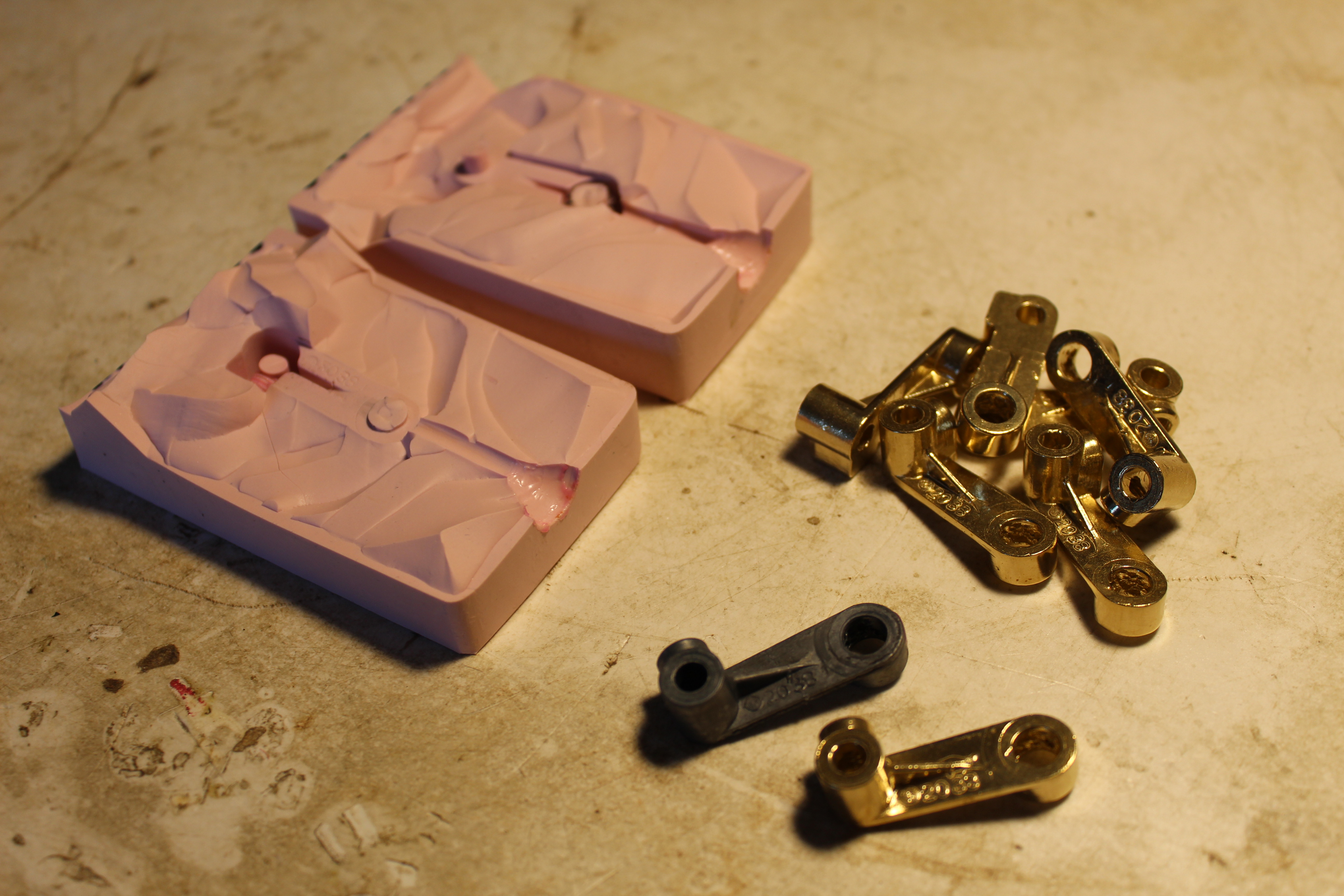
I found a local casting company willing to do small scale orders. Ace Castings in Colchester, Vermont. I sent them a glued-together pot metal linkage and they made me 7 beautiful brass pieces. I ordered an extra one assuming I was going to screw up at least one trying to drill the 3 holes and tap the one for the set screw. But they were able to cast the holes too. I had to slightly ream out some of the holes with a drill bit to get them to fit on the condenser shafts but they all fit perfectly. |
|
|
|
|
But first I had to deal with the warped tuning condensers. All 5 of them. Although the pot metal frames were cracked pretty bad, none of them seemed to be very fragile. The problem was the hard rubber insulators holding the stator plates together. They were warped and had shifted off-center so the plates were rubbing against the rotor plates. |
|
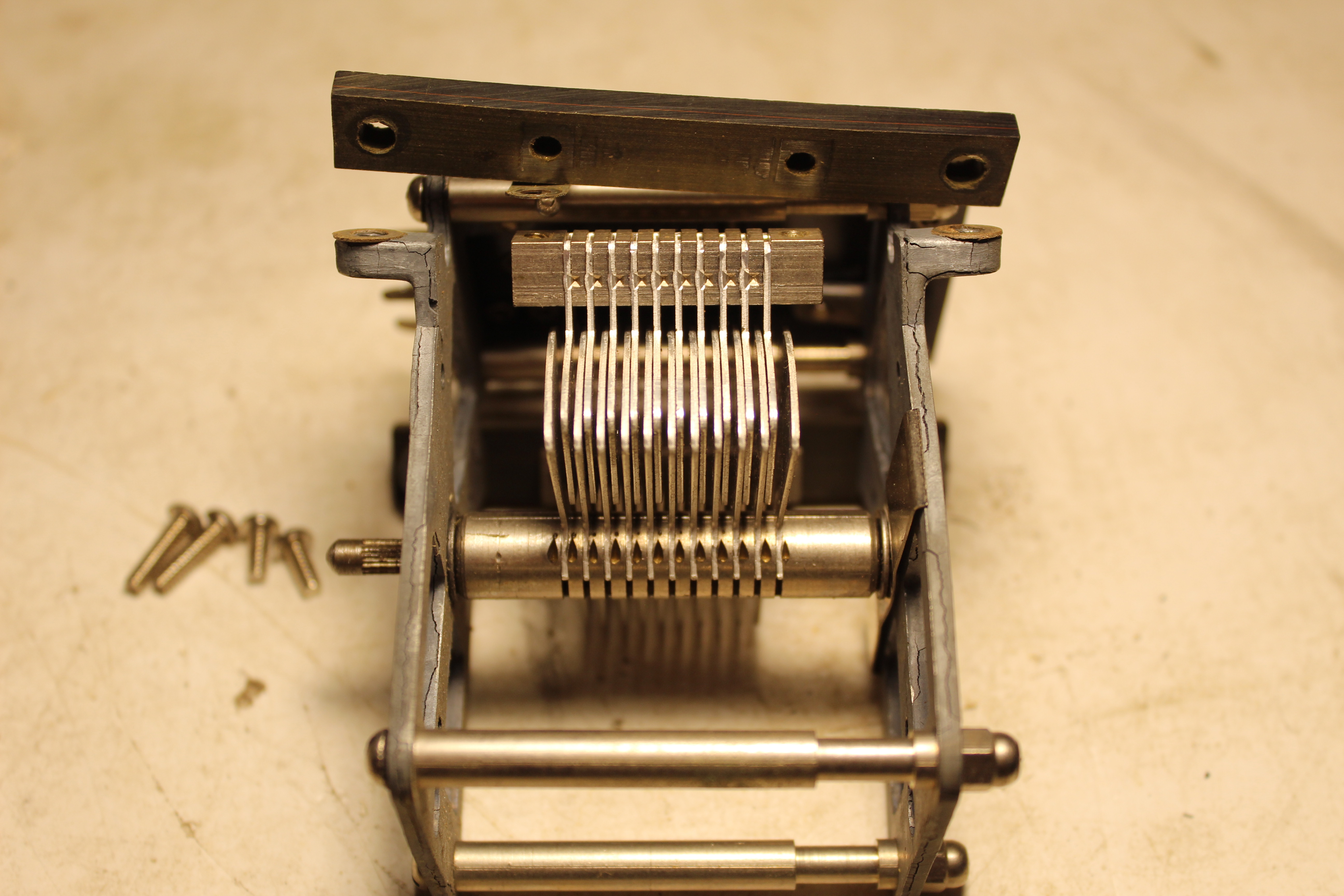
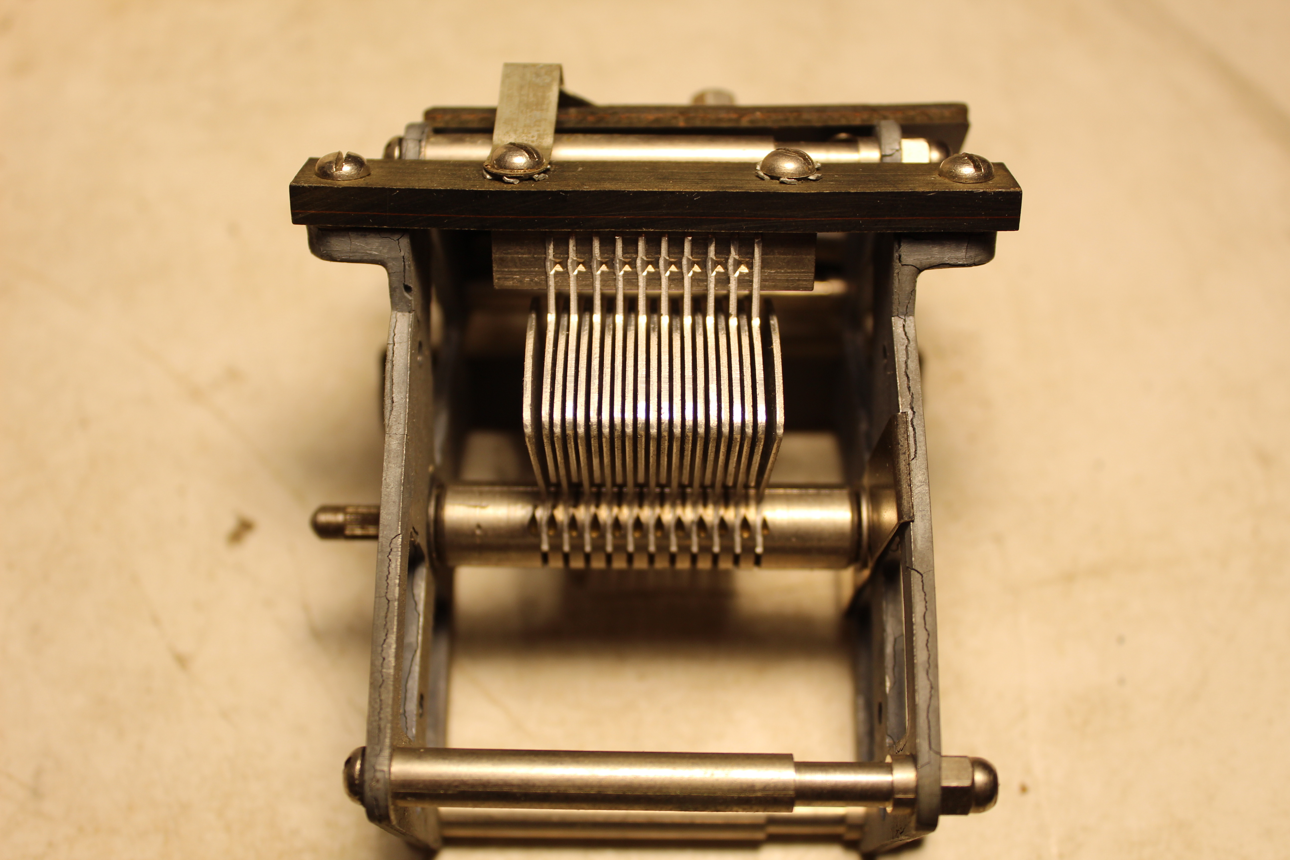 Bad Better |
|
|
I removed the 4 insulator mounting screws and carefully drilled out a slightly larger diameter on the end holes. Just enough to give the insulator a little wiggle room when remounting it to the condenser frame. You can see how fragile those mounting ears on the frame look. I was sure they were going to fall apart with the slightest torque of the screws going back in. But I was able to very gingerly tighten the insulator bar back down with a slight finger pressure on it towards the right. The screws did not break up the mounting ears and the stator plates were now evenly spaced between the rotor plates as they should be. |
|
|
|
|
I re-installed the 5 condensers and then worked up a plan to get the new brass linkages fastened to the connecting rod. The original links were connected to a 'T' shaped metal cylander which was riveted to the rod at the lower narrower end. The wide top of the 'T' held the link in and there were was just enough vetical freeplay for the link to freely swivel around the lower narrow part of the cyclander. |
|
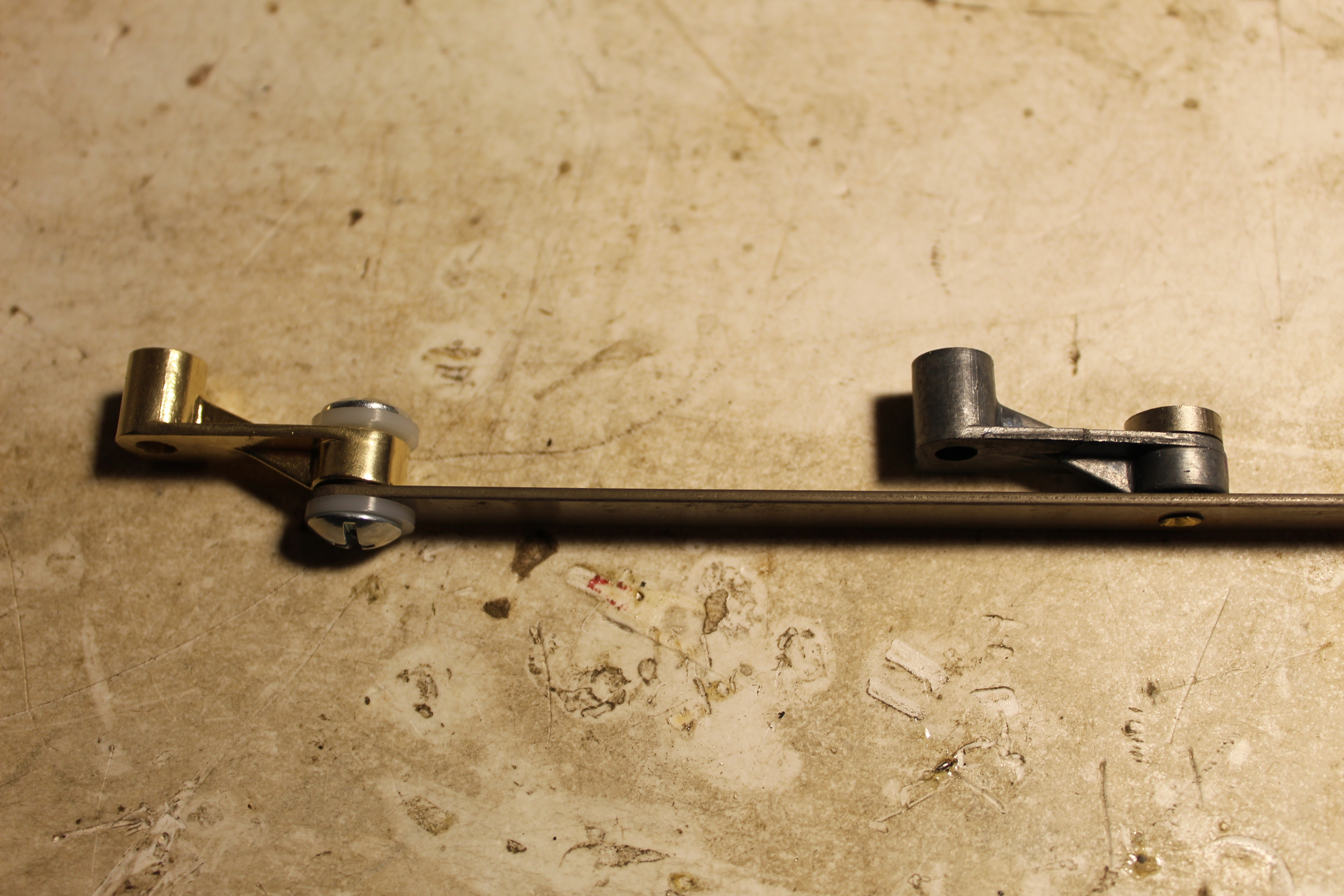 The original linkage on the right, new contraption on the left |
|
|
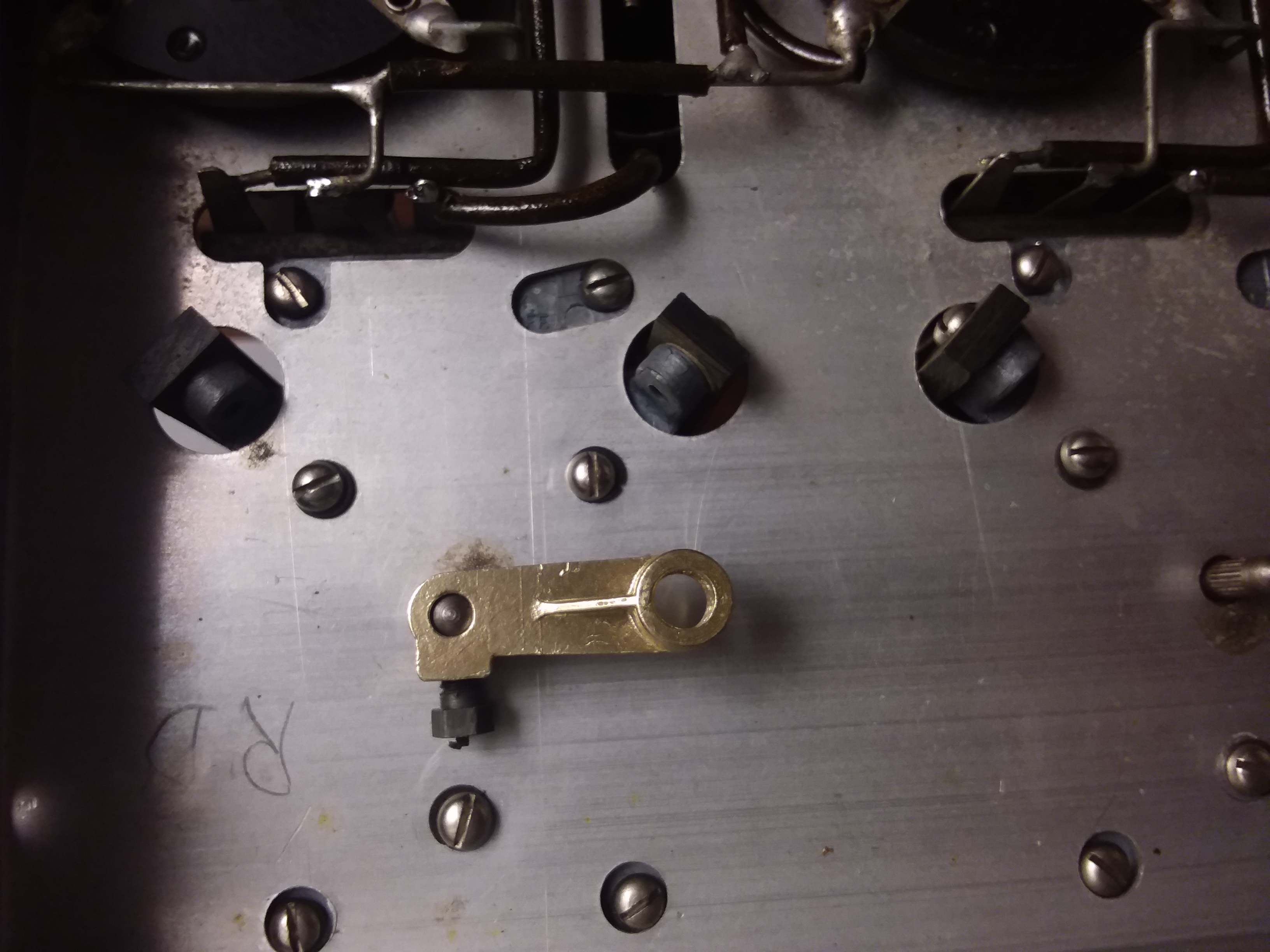
For the new contraption I spent a 1/2 hour on my knees at our Pick & Shovel hardware store rummaging through their trays of Miscellaneous Hardware looking for a suitable equivalent. I came up with 1/4" Screw Posts which should work nicely. The Post mimics the original 'T' cylander. It comes down from the top and holds the linkage in to the rod. It has an internally threaded narrower bottom part on which the new brass linkage piece swivels. Instead of a rivet to the rod, a screw comes in from the bottom to hold the post in place. The only difference is the amount of vertical freeplay. And the fact that the bottom screw can easily become unscrewed and fall out. I tried various numbers of nylon washers to take up the freeplay and got it working very smoothly. I think a dab of Loctite on the screw threads should keep the contraption from falling apart. |
|
|
With the new linkages in I'm able to control the full travel of all 5 condensers with the single dial control. The movement was a little clunky at first, but by playing with the nylon washers and then getting the rig horizontal again I'm getting smooth movement all the way through the condenser movements. |
|
 Before After |
|
|
I wasn't quite done yet. I noticed that a few of the condensers were not exactly aligned so I got back under, loosened the setscrews on the brass linkages and rejiggered the shafts to make sure all 5 were lined up. |
|
| Audio Problems | |
|---|---|
|
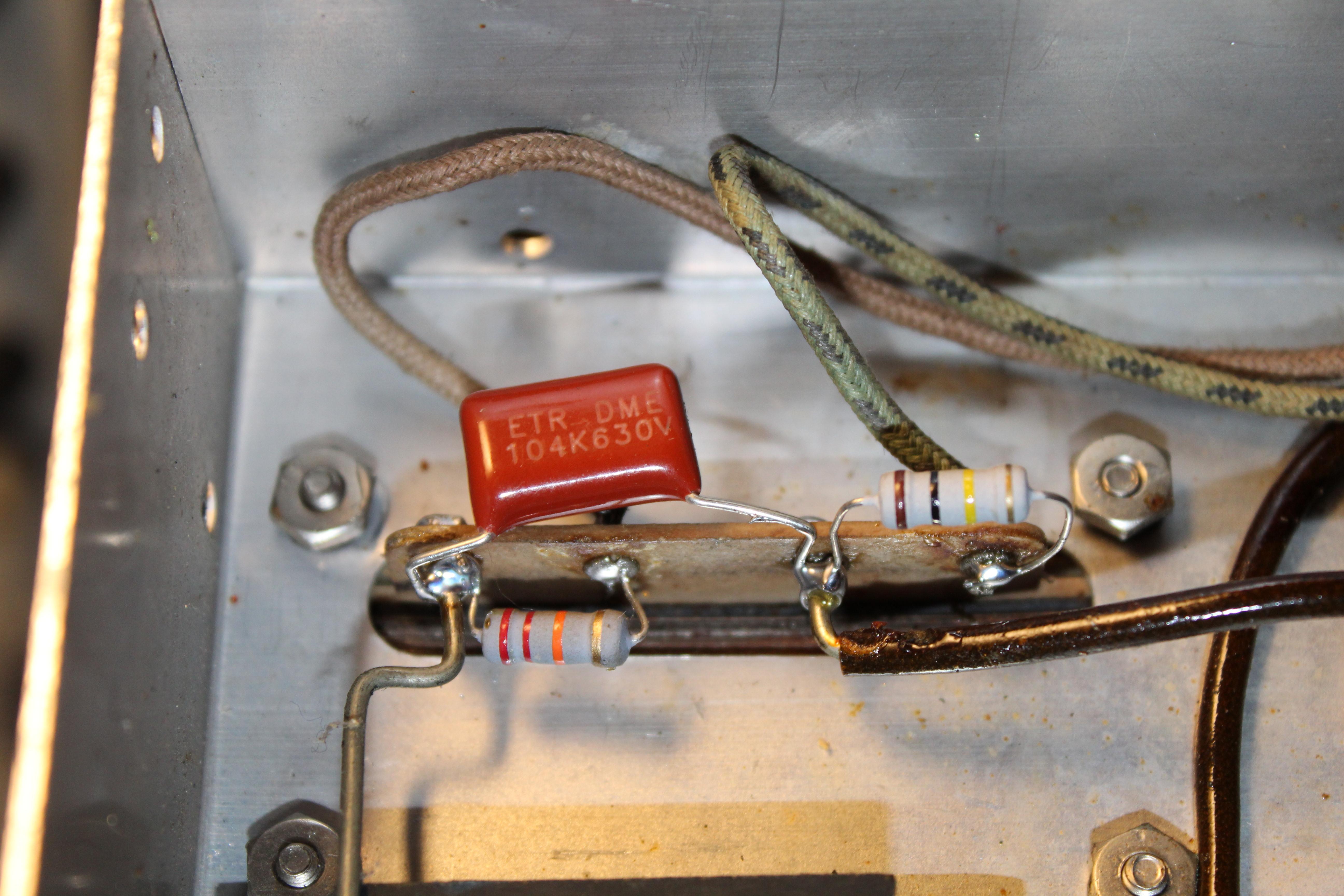
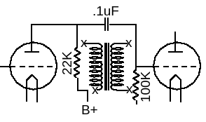
Now that the mechanicals are taken care of it's time to look at the electronics. The first thing to check is the 2 audio transformers. 3 out of the four windings on the transformers checked open with the ohmeter. I don't think I'm in the mood to read up on any threads about re-winding your bad audio transformers so I took the lazy route out and threw in some resistors and capacitors to bypass the transformers. |
|
|
|
|
Many years ago Norman Leal of the California Historical Radio Society published in the CHRS Journal Vol. 19 No.1 pg.29 a simple and effective way to bypass bad audio and IF transformers. I unsoldered the leads on the one transformer winding that was good. On each transformer I put a .1uF across it from driving plate to next stage grid. Then across the input sides a 22K 1 watt and on the output sides a 100K 1/2 watt resistor. |
|
|
|
|
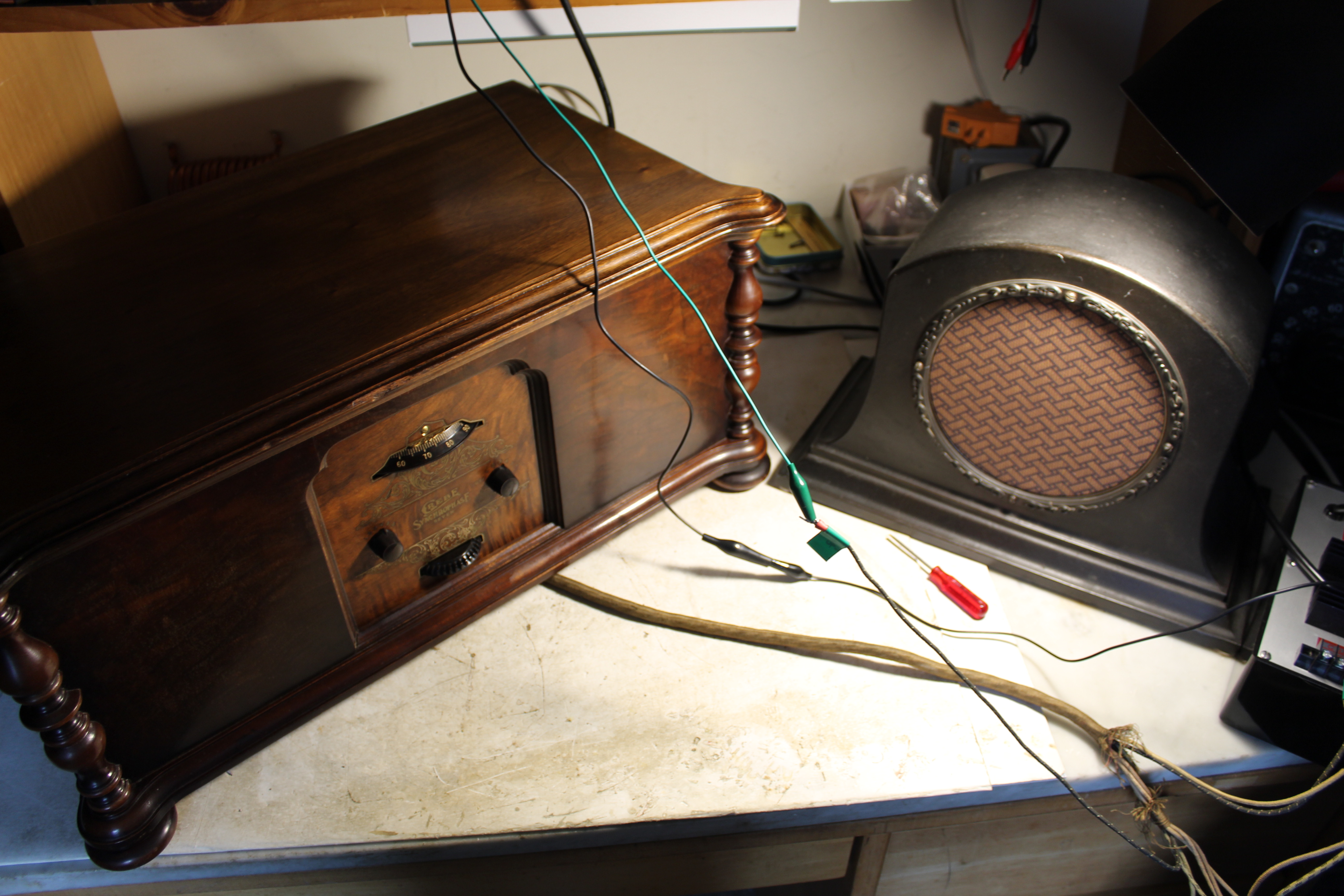
Finally I was ready to put some power to the Grebe. Using a newly acquired ARBE III power supply, (and -40V from the old Heathkit IP-17 which the ARBE can't seem to do) the filaments lit up and on one leg of my longwire doublet antenna all the nightime 50kw clear channel stations came booming through. The top of the dial gets a bit crowded because of the SLF condensers. But it works. It's pulling in stations again. |
|
| The Cabinet | |
|---|---|
|
|
|
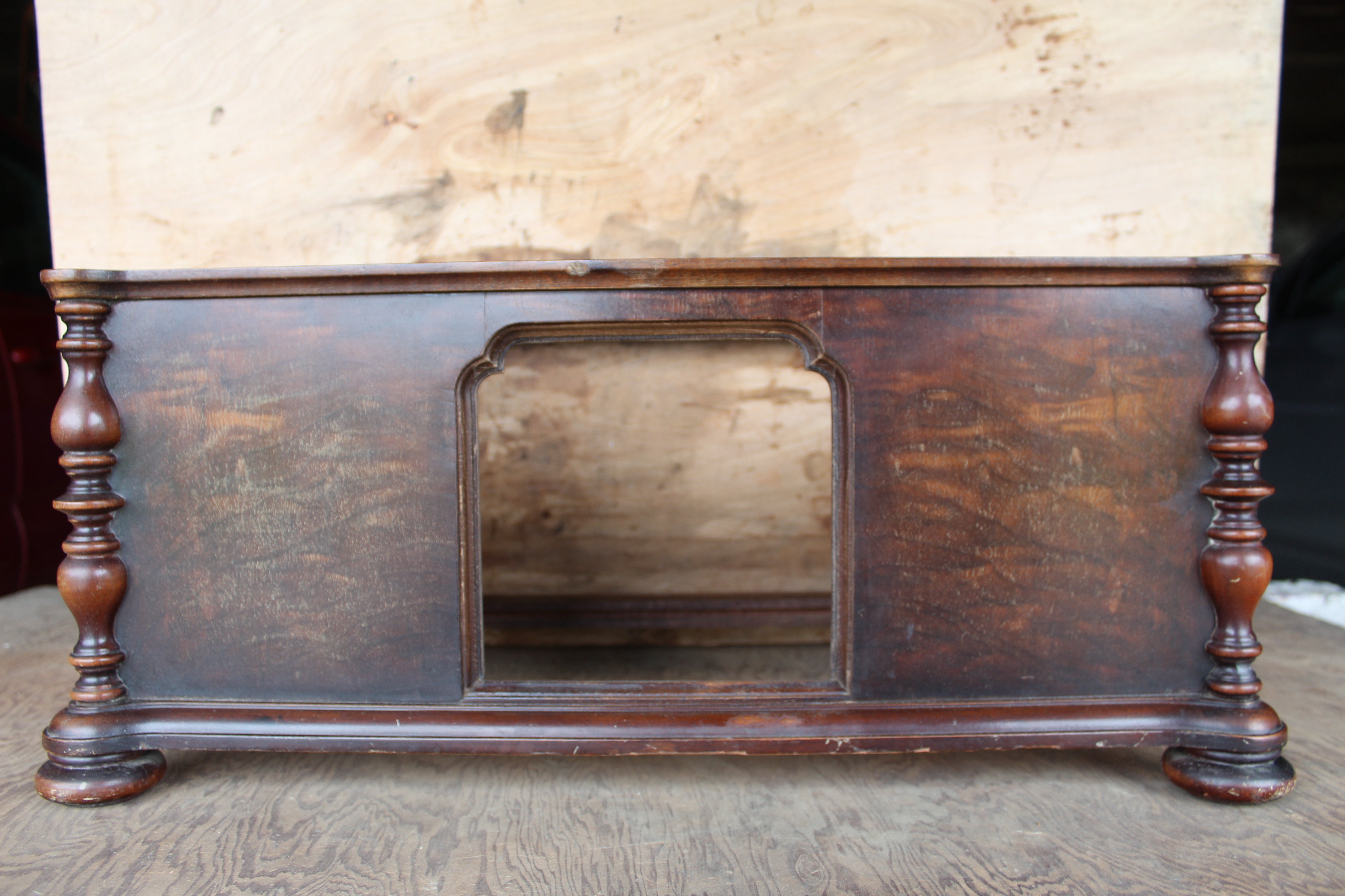
To my inexperienced woodworking eyes the Grebe cabinet itself did not look like it was in too bad shape. The lid had some serious scratches and the escutcheon definitely needed some attention, but I was surprised at how much better the cabinet looked after a light cleaning with a damp cloth and some 409. After consulting the Antique Radios forums I decided to give it a cleaning with some non-pumice GoJo (the white stuff) and then rub in some Lemon Oil polish to revive and brighten the original lacquer finish. |
|
|
|
|
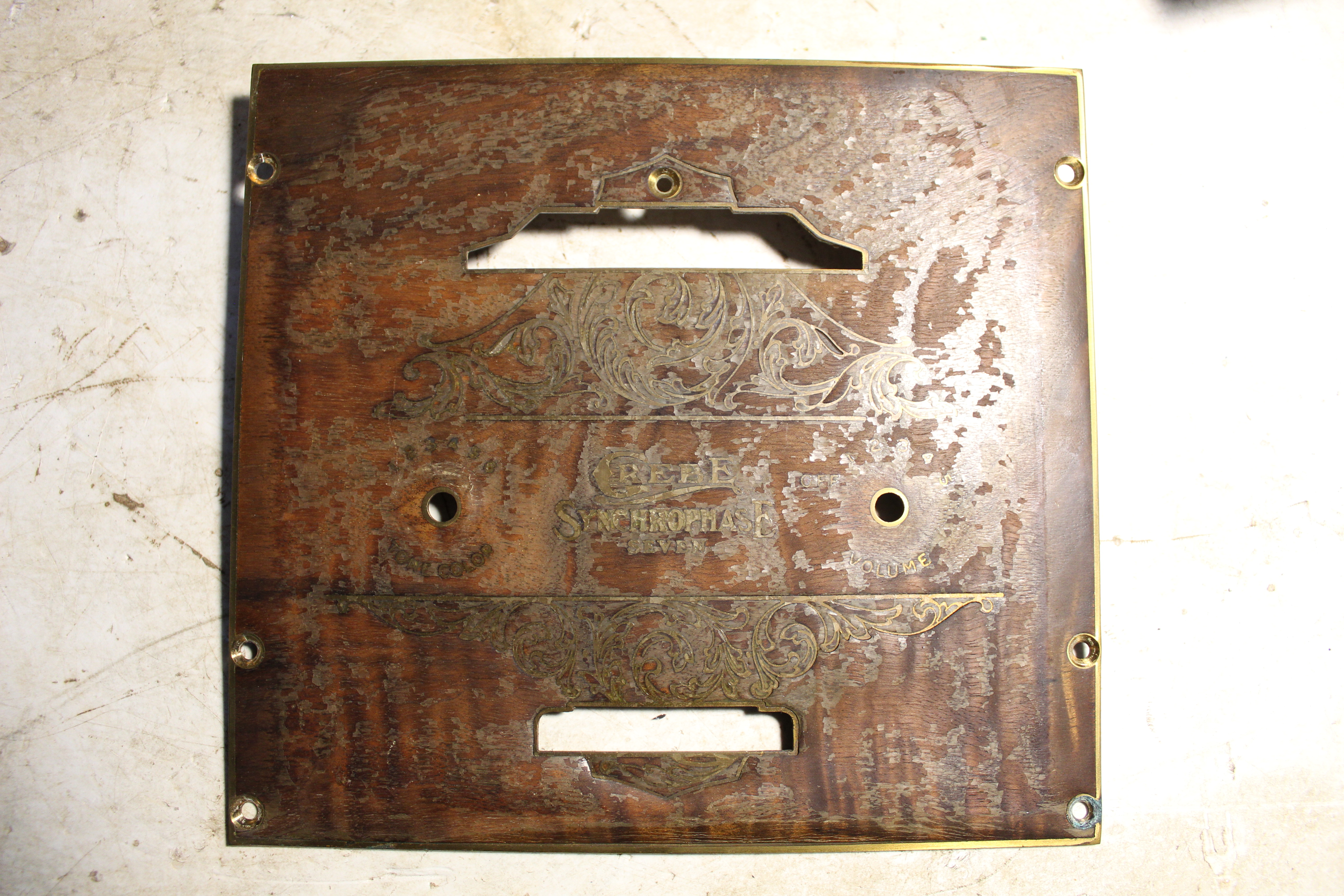
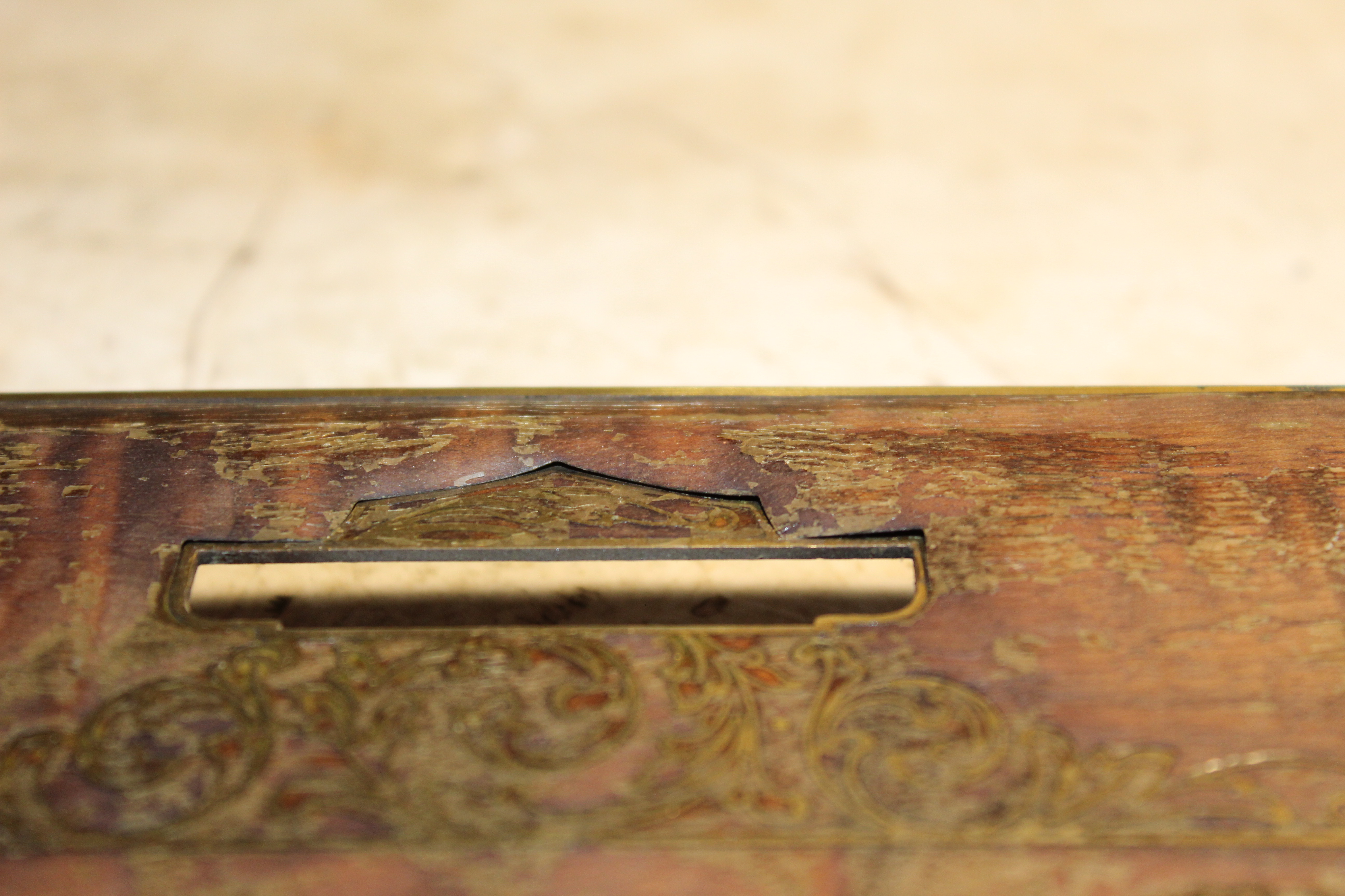
The escutcheon was another story. It's a brass plate with inlaid wood around the raised lettering. Some of the wood towards the bottom of the plate was warped and had lifted up from the plate. I needled some carpenters glue under the raised sections and clamped it tight. That flatenned out the warping but some of the glue seeped out and left sticky\hardish trails that I had to scrape off with some dabs of water and a plastic spudger. The top lid had too many scratches to hide so I stripped it, did some light sanding and then applied a lacquer spray back to it. This was my first attempt at any kind of real wood refinishing, so, I won't show you the sloppy job I did on the undersides of the lid. But overall I'm pleased with it and I'm pleased with the way the whole radio looks. So here it is in all it's glory, clean, shiny and pulling in CJAD's morning talk show from across the border in Montreal. |
|
|
|
|
It's not museum quality but that's not what I'm looking for. A functionally restored radio that works again after 95 years. I think "presentable" is the proper term for me. |
|
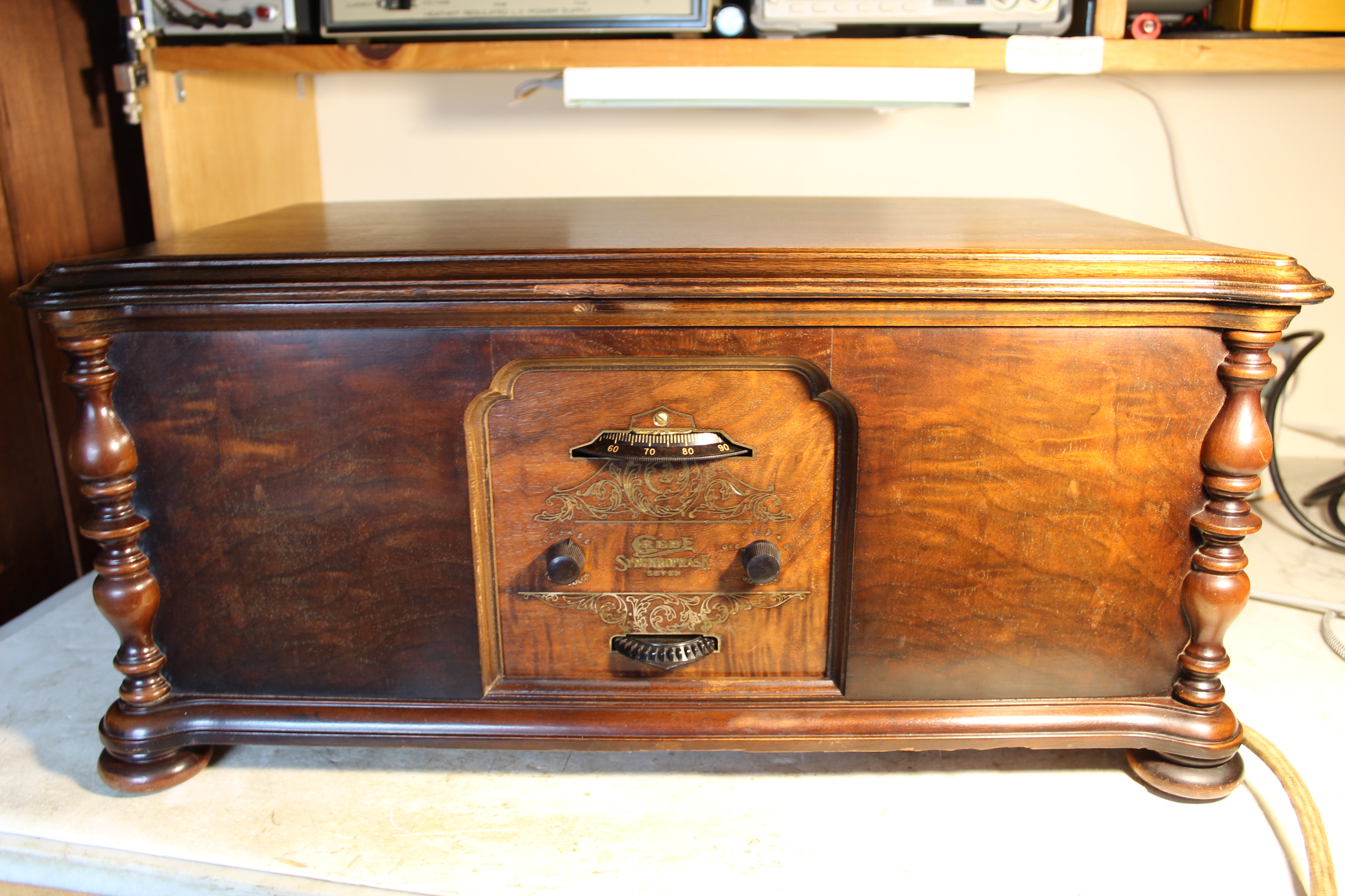 Presentable |
|
 2021 WA2FXM - Mark Mohrmann 2021 WA2FXM - Mark Mohrmann |
 |