Modulator
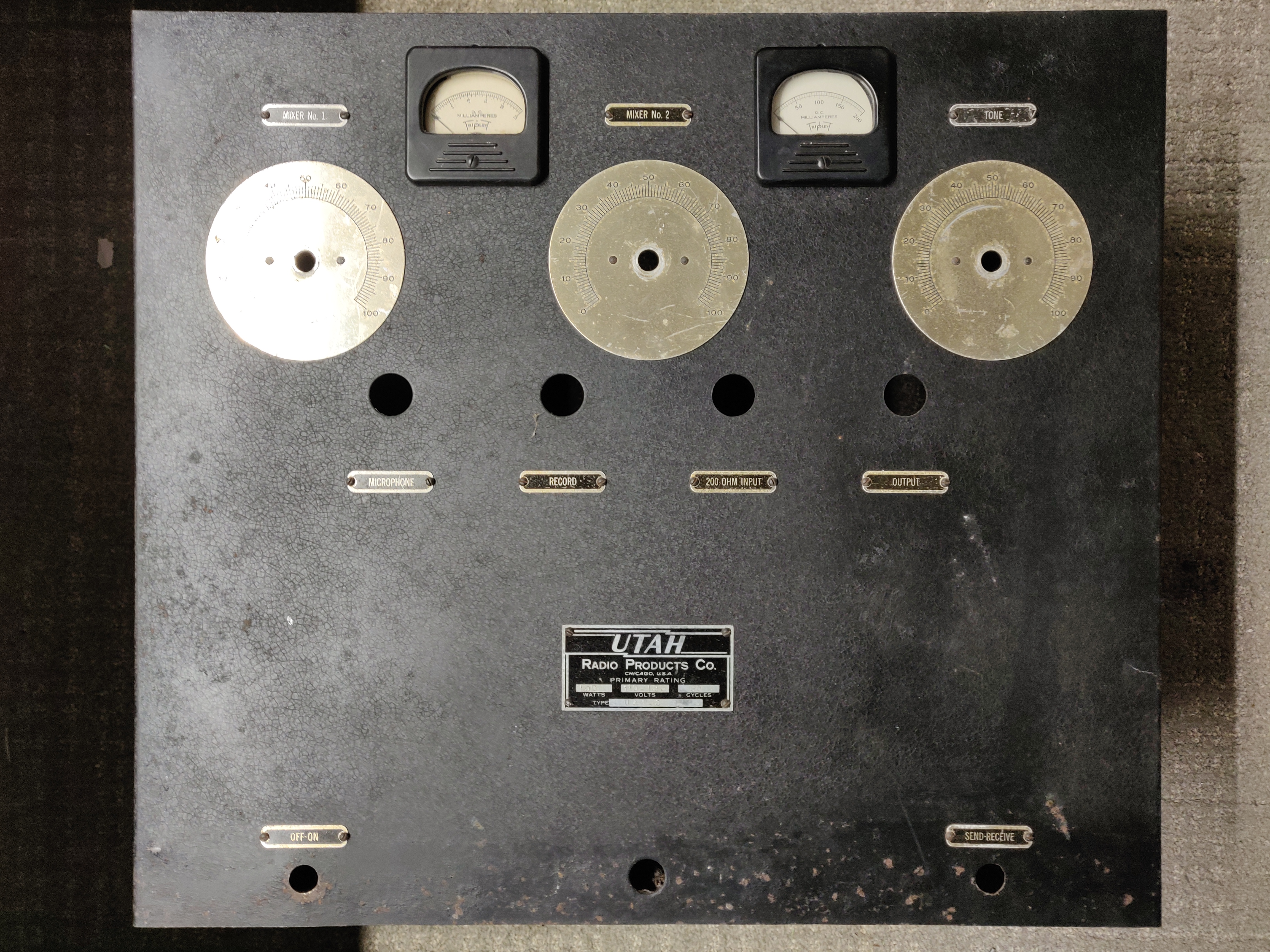
| A Utah Radio UAT-2 Modulator |
|---|
|
|
| The Rebuild | |
|---|---|
|
First Design  |
|
|
There is very little documentation available for the UAT suite of 5 kits. The October 1937 issue of Short Wave & Television has a brief article describing all 5 units. The UAT-2 is described as a class AB modulator with fixed bias and push-pull 6L6's. The tube lineup is given and then that's it. No schematic, no parts list, just a blurry picture of all 5 units stacked up together. If I was going to have a Utah modulator I was going to have to build it myself from scratch. I went back through old QST's and Handbooks from the 1930's and found a likely candidate. My dog-eared copy of the 1939 ARRL Handbook features a 50-Watt 6L6 Modulator project and references the original June 1936 QST article by Assistant Technical Editor George Grammar W1DF. Grammar was all excited about the newly available beam power tube, the RCA 6L6. Using them as modulators he came up with his "50 Watt Audio Amplifier-Modulator Unit". The tube lineup was almost identical to the UAT-2. A 6J7 pentode input amplifier, with push-pull 6C5's driving the push-pull 6L6 modulator tubes. The only difference was the intermediate amp, using a 6C5 instead of the UAT-2 specified 6N7. |
|
 George Grammar's beam power tube 50 watt modulator |
|
|
So with copies of his schematic and parts list I started scrounging around for all the pieces. The junquebox was doing ok until it came to the 3 transformers. I eventually had to rely on eBay for the Thordarson driver and modulation transformers but early on, Mike W3SLK volunteered his 20A23 input transformer which he said he had been carry around for a few decades. I assured him it would be put to good use and started breadboarding the mic amp. |
|
 My First Attempt |
|
|
I was making some progress with the haywire breadboarding of the mic amp. But I was agonizing over what to use as a cabinet to mount the modulator chassis'. When I won the auction for the UAT-1 Exciter box last year, the lot included an empty UAT-5 High Power Modulator cabinet. I'll never know for sure, but my gut feeling is that the innards of that high powered modulator were laying on a table in another bidding lot of miscellaneous "junk". I was considering using this cabinet for my reconstructed UAT-2. I knew I was never going to find the electronics for it. And it was just another metal box taking up space in the shack. But it pained me to think about drilling new holes in this apparently rare piece of radio history. I started to think about building a wooden cabinet. Painted black it would kind of look "cool" sitting next to the original UAT-1. Kind of. |
|
|
______________________________________________________________________________________________________________ |
|
|
I Find Half Of A UAT-2 When George K1ANX came over at NEARFest to admire the UAT-4 amplifier I had just scored and kind of cryptically seemed to mention he might have some "information" for me about Utah Radio Products I had no idea he actually was in possession of a modulator cabinet with the power supply. After a few emails back and forth we made arrangements to meet and I came home with the half empty cabinet. The power supply looked like it was in fairly decent shape. But I immediately realized there was going to be a problem with the empty upper shelf of the cabinet. |
|


|
|
|
Utah Radio Products used very shallow chassis' in all of the cabinets I've seen so far. They are exactly 1 inch high. Which gives you exactly 7/8 of an inch space to cram components in on the underside. That in itself would become a problem later on with the UAT-4 Amplifier box. But the problem with the modulator was my chassis was too tall. That Thordarson T-8470 modulation transformer was too tall to mount on my 2-7/8 inch chassis. That chassis was the first piece I acquired for this modulator project. It was originally someones homebrew 10 meter AM rig, with tiny little modulation transformer and a gnarly bent up 10 meter coil. I was sure it was going to be the perfect chassis for the modulator audio deck. I even got it all cleaned up and painted crinkle black. But alas, it was not to be. The Thordarson transformer barely fits on the upper shelf by itself. I was now going to have to consult the chassis scrap heap again to find a shortened one that would fit next to the free standing modulation transformer. |
|
 The Chassis Scrap Heap |
|
|
______________________________________________________________________________________________________________ |
|
|
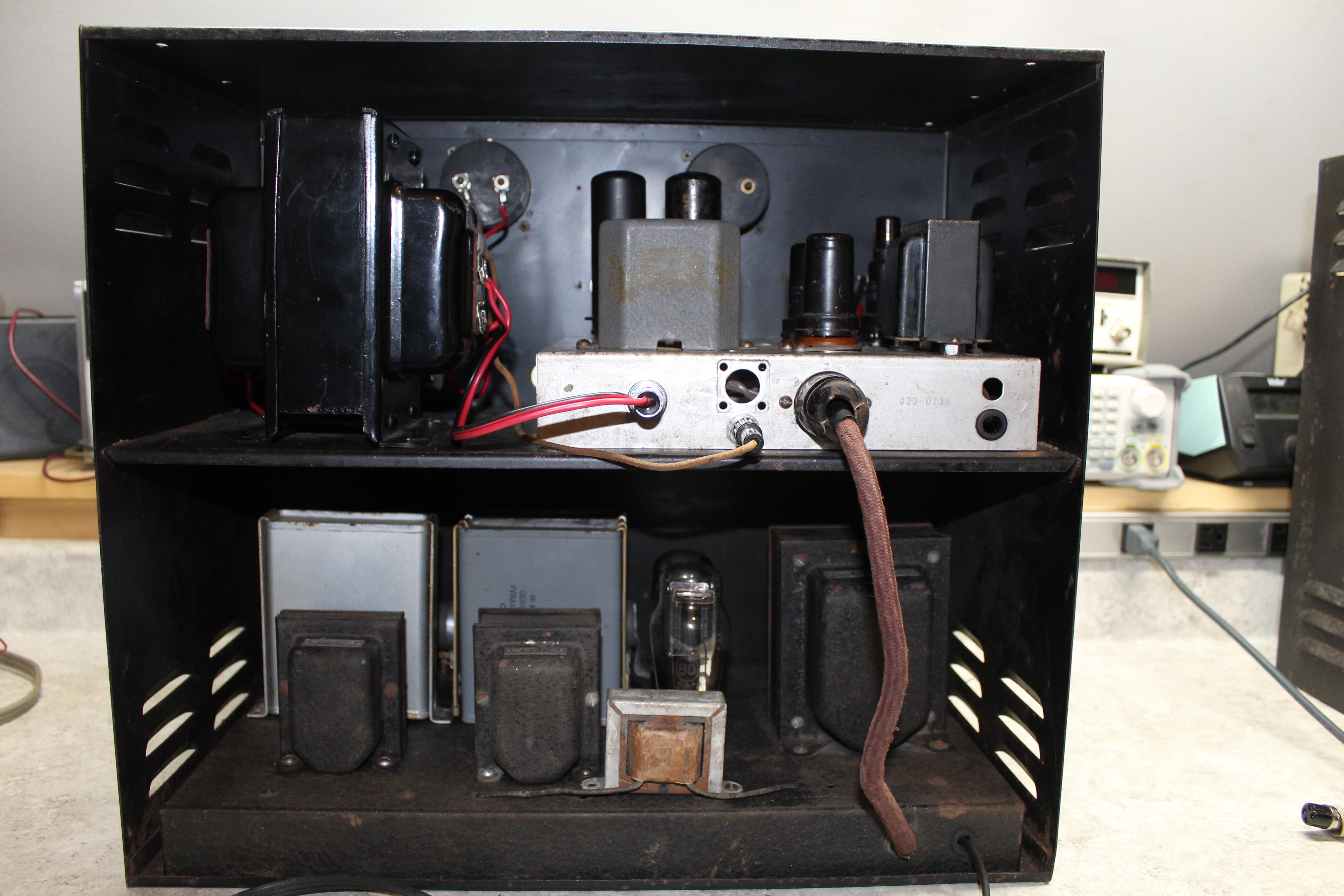
Starting Over With A Power Supply I put the amplifier breadboarding on hold and concentrated on the power supply. Again, I was flying blind. Without any documentation I had to trace out the wiring myself and see if it made any sense. I moved along through the components measuring values and coming up with a schematic. On the plus side, I didn't find any obvious shorts. On top the plate transformer and filter chokes all showed reasonable resistance values. Two of the filter caps measured low and the bleeder resistor which probably should have been in the 50K range was measuring way too high. It wasn't clear to me where the bias voltage was coming from at first. And the big, ugly, dirty relay with the rusted, insulated screw-in bolt at the end of a connecting wire was meant to screw in somewhere. I took the relay apart, cleaned it and it worked with 120VAC across the coil. Maybe a homebrew T/R switch to the audio deck?. Who knows? I don't have a UAT-2 Modulator Audio Deck to see where it might go. |
|


|
|
|
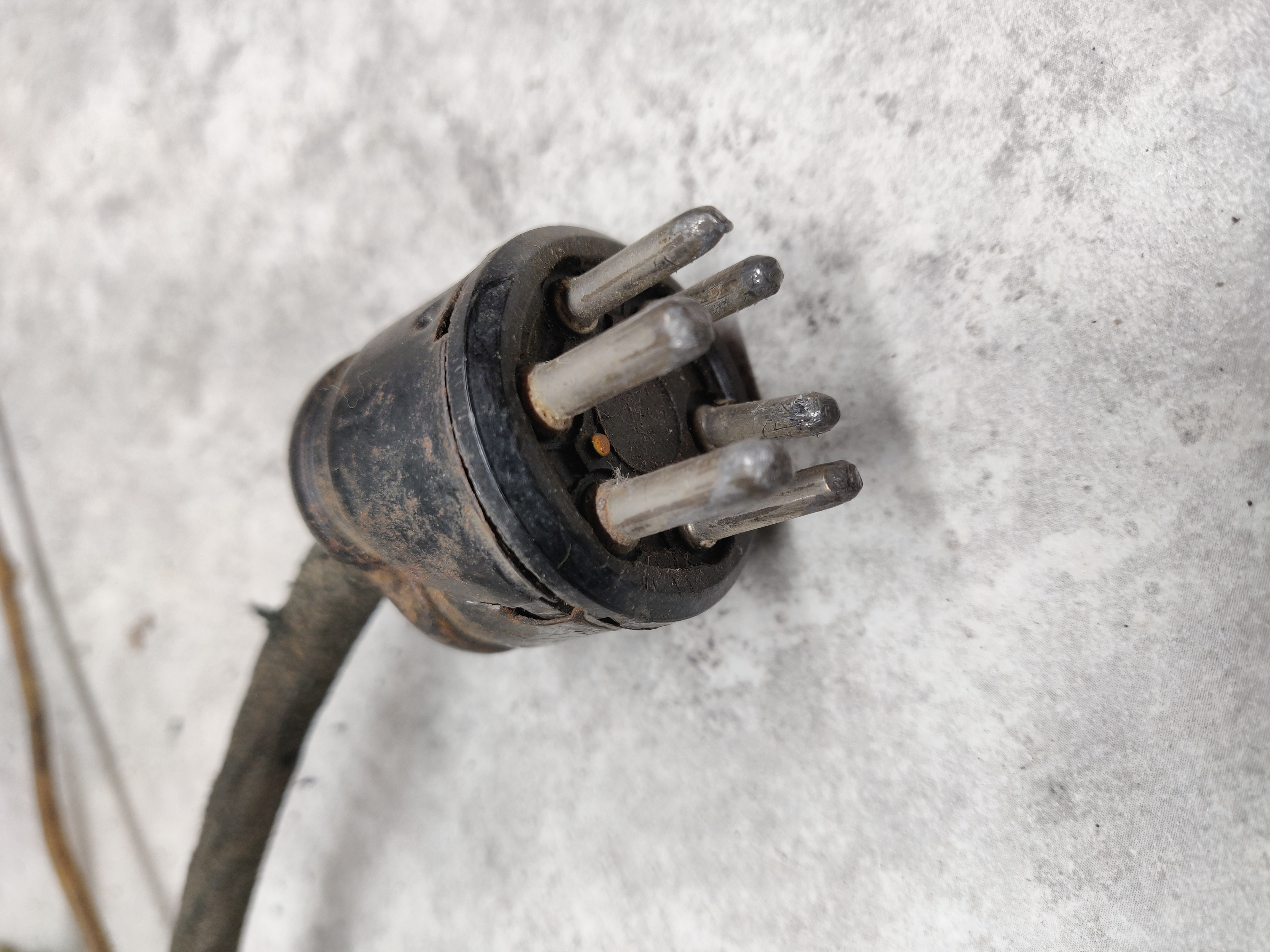
Underneath the 2 orange paper filter caps for the bias supply needed replacing. Nothing else was obviously amiss here. On the back, the power cord had to go of course, and the 6 pin plug presumably made to mate with the audio deck needed a little straightening out. Time to get in there and start bringing this power supply back to life. |
|

|
|
|
I replaced the power cord, bypassed the 2 bad filter caps up top with new electrolytics underneath, and found a marginal 60K wirewound resistor that I kludged in for testing. I replaced the bias filter caps and bent back the pins on the power plug. The 80 and 5U4 rectifiers both tested good so I plugged everything in to the Variac and brought it up slowly with the Send/Receive switch off. The front panel #46 lamp and the rectifiers lit up. I switched to Transmit and measuring at the Power plug I got 558V at pin 4 for HV to the 6L6 modulators and 410V at pin 3 for LV to the audio tubes. |
|
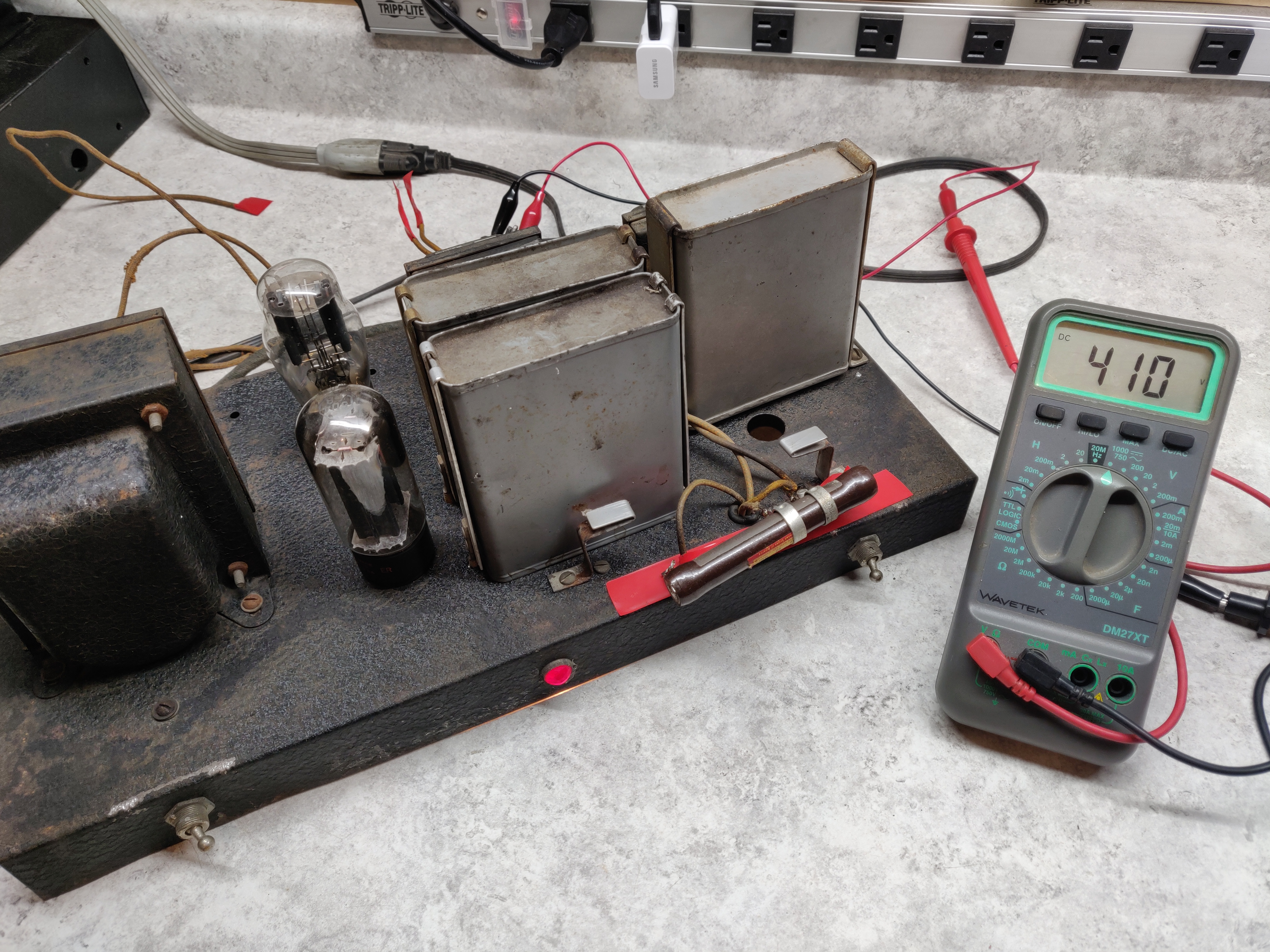 Looks Good On First Power Up |
|
|
______________________________________________________________________________________________________________ |
|
|
Residual Hum |
|


|
|
|
The chassis I finally found was from a discarded CB radio. I depopulated it and started drilling even more holes in it to fit the modulator pieces. I tested it stage by stage as I went along, first the 6J7 mic amp. I know I once built a transistor Class A audio amplifier back in school many decades ago. The only reason I know that is because I still have the lab notes to prove it. With a big A+ scrawled across the top of the page. If you asked me to do it today I wouldn't have a clue where to start. Similarly, I've never built any tube amps so I didn't know what to expect as far as performance in the testing stage. So of course I became obsessed with the problem of 60 cycle hum in a tube microphone amplifier. |
|
 |
|
|
The grid cap for the 6J7 was a junquebox special. There was no shielding on the stub of wire that was hanging off the cap. I got some braid and covered the 2 inches of unshielded wire and soldered it to the coax going back to the mic jack input. My heart sank as I would wave my hand around the grid cap and listen to the hum increase as I came closer to the cap. It would be awhile before I could convince myself that there was such a thing as "residual hum". Having spent most of my adult working years in television and radio broadcast facilities I knew there was no such thing. You turned up the gain and you heard residual room noise, air conditioning fans, people mumbling out in the hallway. You did not hear any 60 cycle hum. None. I spent a lot of time adding .01 capacitors to filament lines, shortening grid wires, adding a single ground point bus bar, putting "humdinger" pots at the filament transformer center tap, grounding and ungrounding metal tube shields, tightly rewinding, rerouting and rewiring the filament lines to the tubes multiple times. I even made a tin foil hat for the 6J7 grid cap. Pressed tight to the ground braid it actually made a huge difference in lessening the audible hum. I was getting a lot of good advice from the AMFone Technical Forum group. It was only after going through all of these filtering gyrations that they convinced me that I was probably going to be ok. It was just residual hum. So I moved on down the chain. Adding each tube and checking the output with a scope and a speaker. The signal on the scope kept getting bigger and the sound louder in the speaker. I assumed that was a good thing. There was also a spot on the gain control where I could overdrive everything which I also thought was good to know. |
|
 |
|
|
I finally got the courage to haul the modulation transformer onto the table and plug in the 6L6's. I lashed a milliammeter to the plate line and a large variable wirewound ceramic resistor on the output. I set the clamp for 3.5K ohms to mimic the load it was going to see from the parallel 6L6's in the UAT-1 Exciter. The 5k to 8 ohm speaker transformer hung off of the load resistor, two padding resistors hung off of this, and the headphones were clipped onto the padding resistor bare wires. Not a shielded wire in sight. |
|
 A new outboarded bias filter choke |
|
|
I brought the power up and before I could even get the headphones on I saw a huge 60 hz sine wave on the scope. Nothing residual about that sine wave. I traced it back to the bias supply. The original Utah filter choke was unlabeled but had "4661" penciled in on the top. I checked a Utah catalog which said this was a 10 Henry 30-40 mil filter choke. I measured it and found only 2.5 Henry's. The junquebox rescued me again with a Stancor 16 Henry replacement. It wouldn't fit in the 7/8 inch space underchassis so I outboarded it up on top. The sine wave went away. But when I finally got the headphones on the residual hum was joined by a rushing white noise. The noise was only there with the modulator transformer hooked up. I was just about at my wits end. All I could think of doing was installing everything in place and hope that somehow the metal cabinet would shield and cancel out all the hum and noise. Which it did. Somehow, miraculously. The gurus at AMFone Technical Forum were right. Residual hum. |
|

|
|
|
I added some plugs and jacks to the rear panel to make separating the standalone modulation transformer and chassis easier. I had to modify the UAT-1 Exciter a bit. I hardwired its plate meter to the final plate line so that I could use the "Output" jack for the modulator input and still be able to read final plate current. I plugged the Variarm into the UAT-1, the D-104 plugged into the UAT-2, and with the HQ-180AC warmed up on the 40 meter band, and I worked Pete W1FEA down in Concord, N.H. He said the signal was S7 doing "quite well". But his takeaway phrase was there was "no distortion" in the audio. And he made no mention of any hum. Residual or otherwise. |
|
|
______________________________________________________________________________________________________________ |
|
|
May 2024 - The Original Utah Radio Products Manual Appears Thanks to Joe W3GMS who sent us a copy of the complete original manual for the UAT-1 which includes schematics of the entire 5 unit UAT suite. |
|
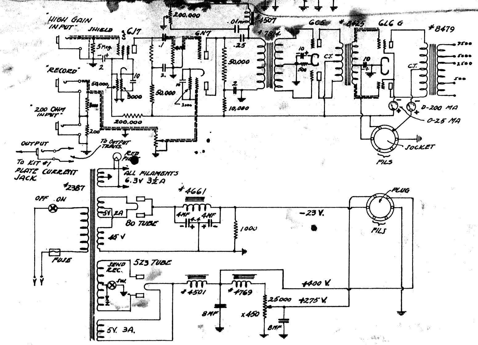 UAT-2 Section of the Original 5-Unit Schematic |
|
 2023 WA2FXM - Mark Mohrmann 2023 WA2FXM - Mark Mohrmann |
 |