Amplifier
| A Utah Radio UAT-4 Amplifier |
|---|
|
|
| The Rebuild | |
|---|---|

|
|
|
The Power Supply Starting with the power supply it took a little work to get the chassis free. A large amount of rust and corrosion around nuts and screws. Lots of WD-40 and patience when slowly, 1/4 turn at a time, removing the nuts. |


|
|
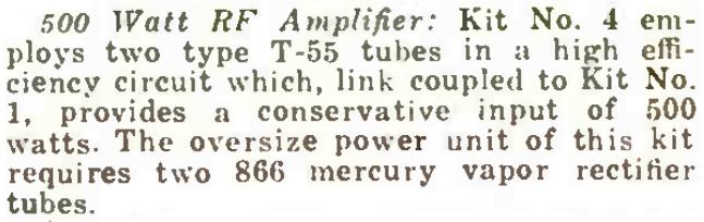
Two beautiful glass etched Taylor 866's. Both with loose bases and plate caps. I pulled them out, cleaned them up, superglued the loose parts together and put them on the shelf to stare at every once in awhile. |
|

|
|
|
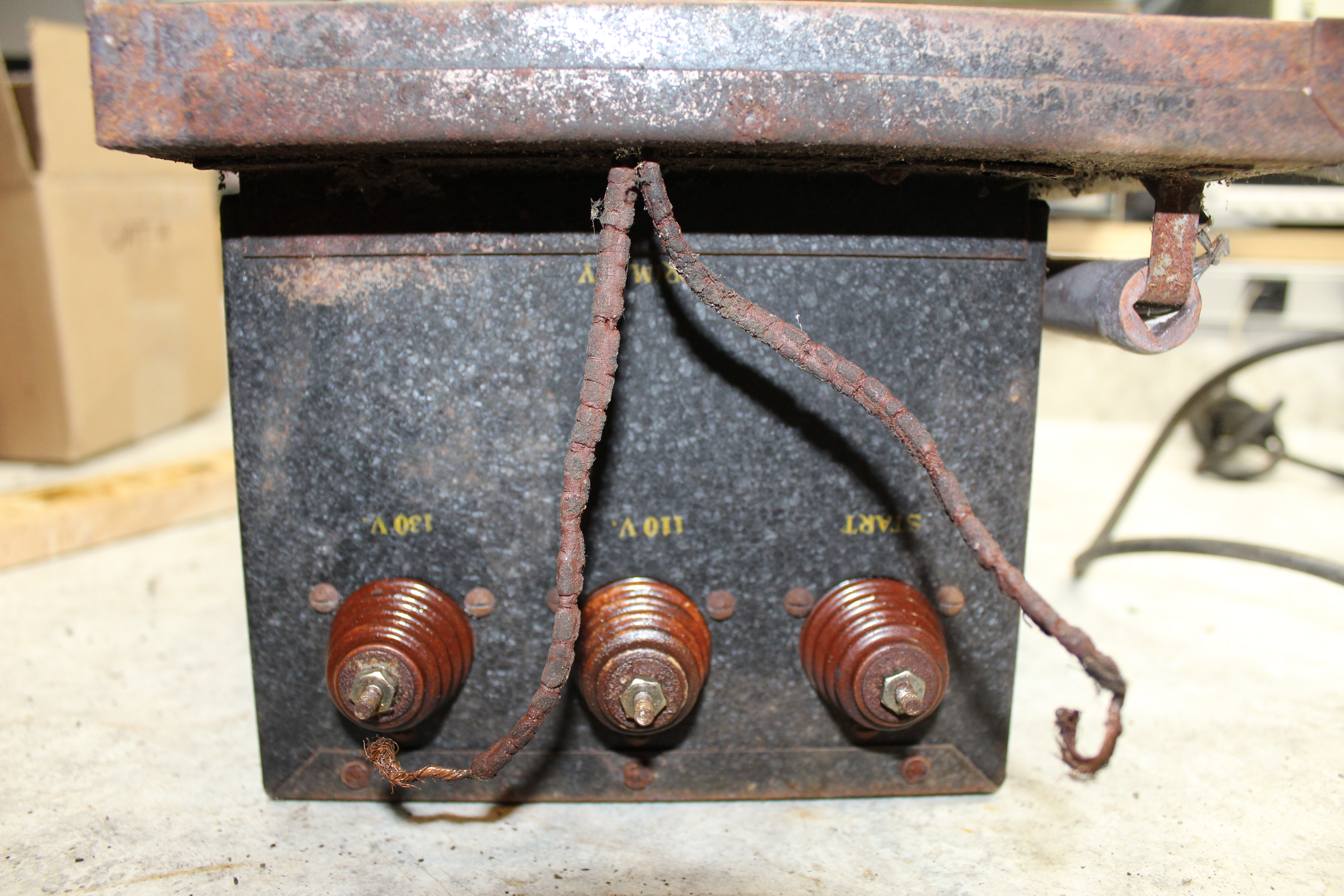
Cracked plate wire insulation will need replacing but underneath decent cloth covered wires should be ok. |
|
|
|
|
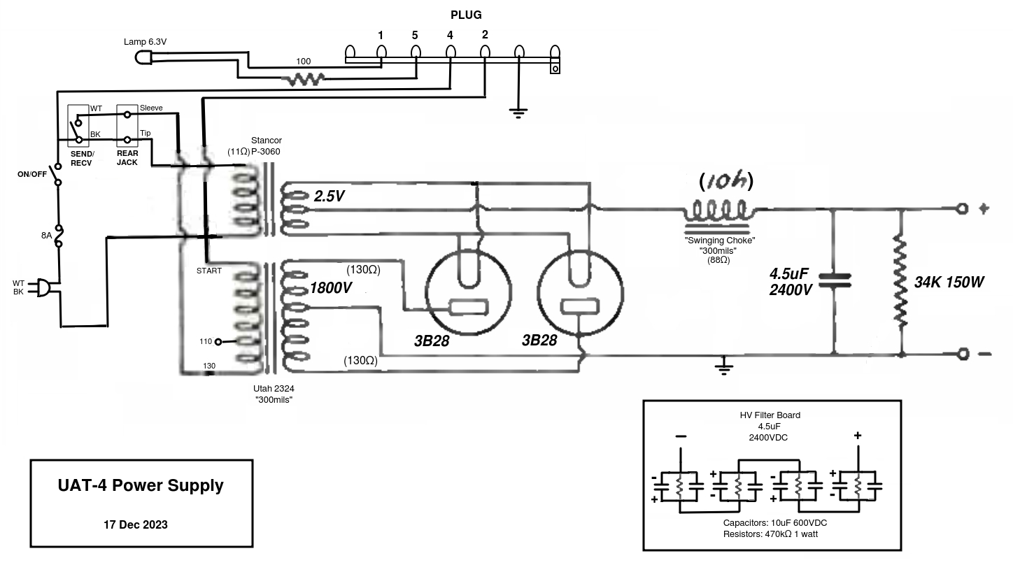
The power cord was replaced with a nice tight fitting grommet at the chassis hole. The cracked insulation plate transformer wires were replaced. Both switches unstuck and cleaned. The bleeder resistor replaced with the only available one around, an oversized 150 watt partially broken variable wirewound. The most I could get out of it is 33K ohms. That will have to do for now. Finally I pulled two 3B28's from my tube stash and plugged them in. With the new power cord plugged into the Variac I slowly brought it up and as my Simpson 260 approached 600 volts I realized I didn't have any voltmeters large enugh to handle the 1800-0-1800 plate transformer. My go-to Wavetek DVM finally gave up the ghost a month ago so I've been using the trusty old Simpson. But it only goes to 1000V (if you remember to switch the red probe to the right jack). Ok, at least I'm getting some voltage out of the plate transformer. I looked around and saw the HP410 with its 1500V voltage switch position so I hooked it in and tried again. This time I got up to about 900 volts when there was a sharp crack and buzz coming from somewhere in the middle of the power supply chassis. No smoke or smell but something happened. I measured close to a short across the the bleeder resistor. Which disappeared when I disconnected one of the old Aerovox 2uF 2000 volt filter caps. So we're on hold now as I've ordered a handful of 10uF 600 volt electrolytics to build up a replacement filter cap. Well that was stupid. My desire for historical authenticity trumped my common sense and the shorted old Aerovox capacitor took out one of the 3B28's. |
|
|
A High Voltage Filter Board The parts came in and I built this filter board to replace the 2 Aerovox filter caps. After testing it for total capacity I added 470k ohm balancing resistors across each of the 4 pairs of 10uF 600V capacitors. |
 
|
|
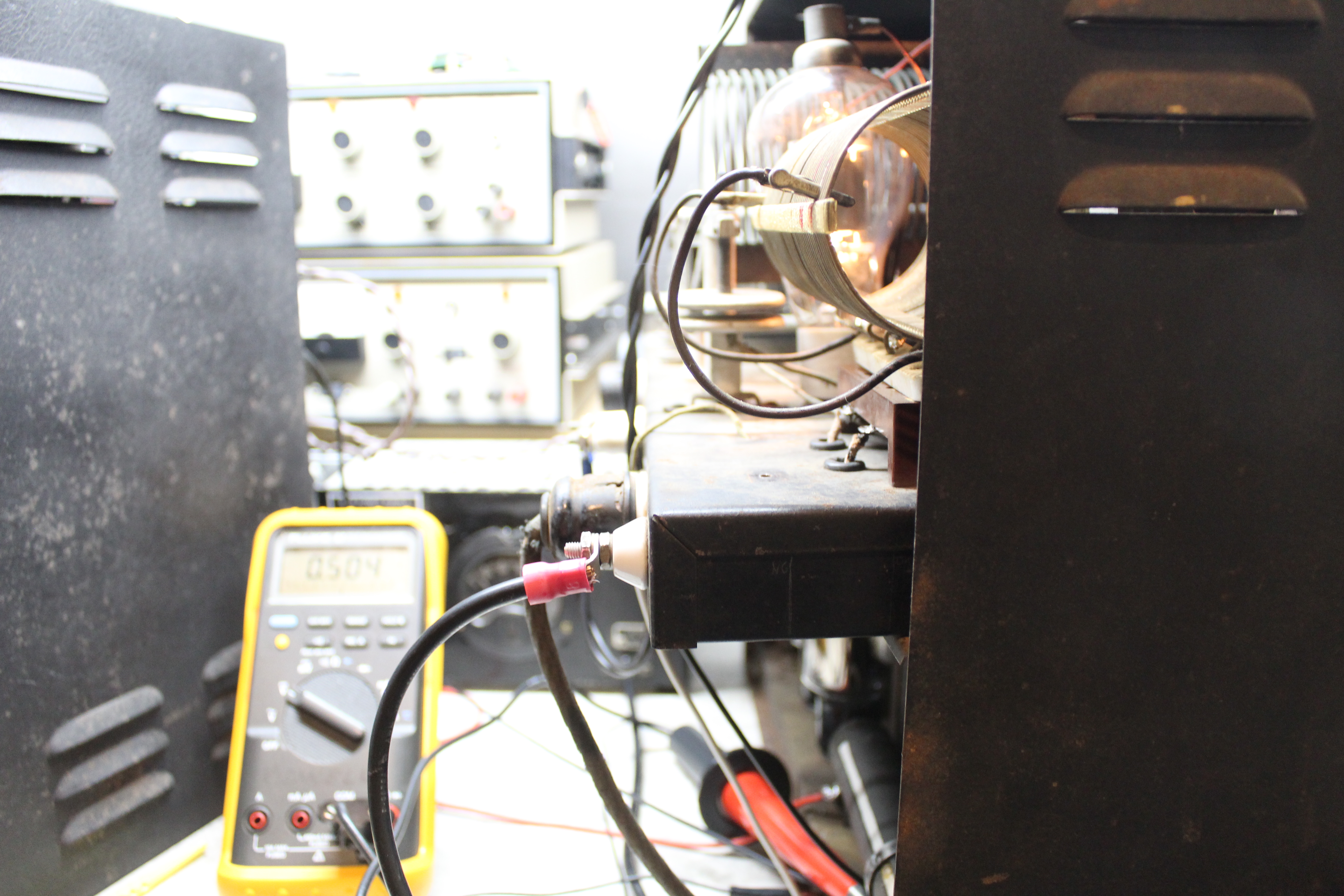
I mounted it in between the plate transformer and the original capacitors. A couple of little 'L' brackets on the perfboard held down by two of the plate transformer mounting bolts. I re-routed the ground and HV wires to the new board and I plugged the power cord into the Variac. I can't tell you how hard it was to crank up the Variac as I watched the voltage slowly creep up on the Fluke as the chassis hum started getting louder and louder. I've never had anything like a 2kV power supply, open to the air, sitting live on my bench. It took about half a dozen tries inching the Variac inch by inch and then pulling it back down before I finally got the nerve to move it up to 1800 volts. No smoke and no bad sounds. |
 |
|
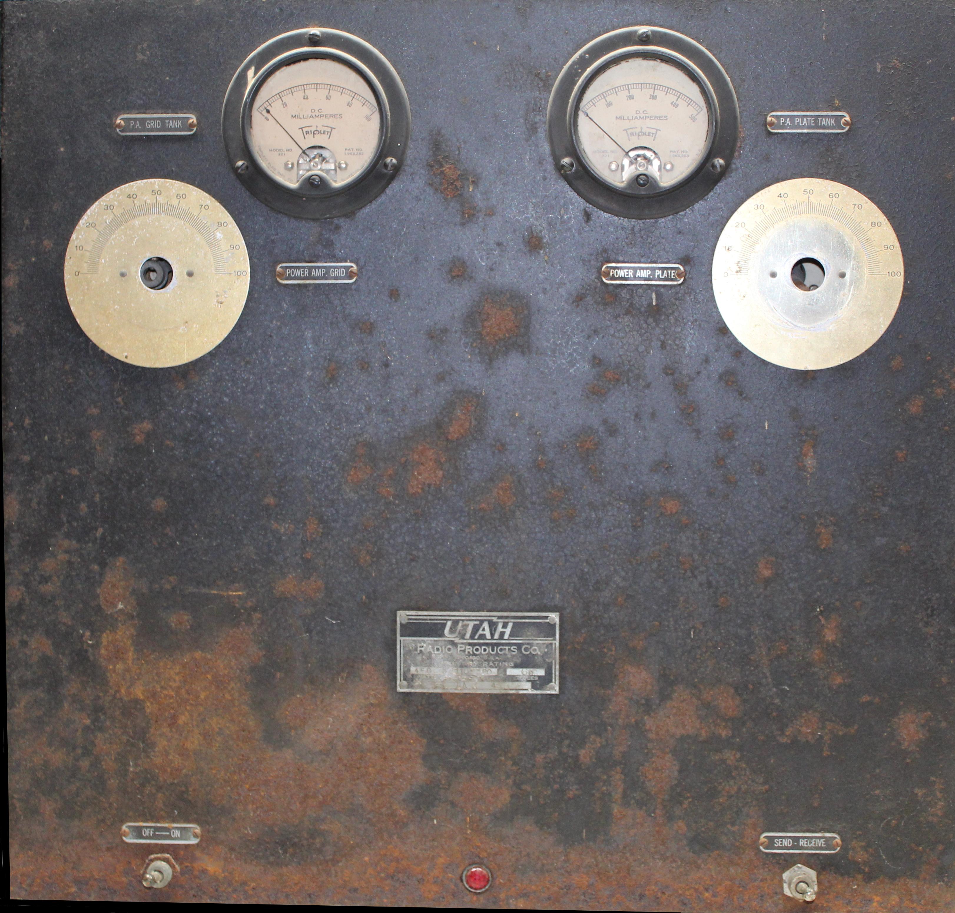
The 5-pin power cord to the RF deck carries switched 117VAC from the On/Off switch for the T-55 filament transformer. It then uses two more pins to bring the 7.5V back down to the power supply, through the 100 ohm wirewound resistor for the 6.3V power lamp. There's a 1/4" jack on the rear chassis that might be for a remote T/R swich but it's been rewired to just act as a tie point for the Send/Recv switch and the plate transformer primary. So the only question I really have right now is how did they bring the 1800VDC up to the HV connector on the right side of the RF deck rear panel? The hot end of the original bleeder resistor, which is right below the HV connector showed no signs of connecting a high voltage cable there. Maybe a spade lug terminal and HV wire coming off of the filter capacitors? |
 |
|
One more thing on the power supply. I fused the AC input. It suddenly hit me the other day I shouldn't be cavallierly powering up an 87 year old 1800 volt power supply without at least a modicum of protection. Fusing wasn't a thing back in 1937. It would be a year later before Edward V. Sundt would found the Littelfuse company. But back then the parts were brand new and you didn't worry about worn insulation, moisture infiltration, or just plain overuse. |
 |
|
So I squeezed a fuse holder into the 7/8" space that Utah provided under the chassis. I feel a little bit better now about powering the beast up. |
|
The RF Deck |
 |
|
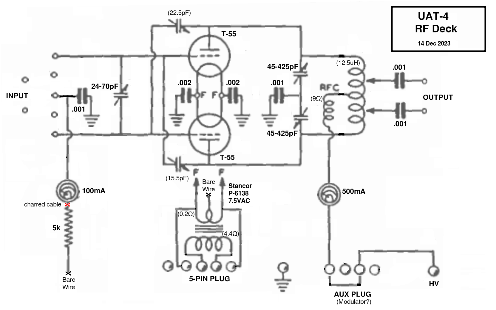
The RF Deck comes with a few anomolies that is going to make it a little harder for me to figure out how the amplifier is put together. It seems to be a standard late 1930's push-pull Class C RF Amplifier. Not because I'm at all familiar with these amplifiers, but it seems to follow the general pattern of all the amplifiers in QST and the ARRL Handbooks of the era. A plug-in grid coil (which is missing) with a not-split tuning capacitor, tied to the T-55 grids with appropriate neutralizing capacitors going to the plates. A fixed split plate tank coil with an unusually large split tuning condenser, and the coil tapped with two movable clips tied to the output antenna connectors. |
 
|
|
So right off the bat I see two things to wonder about. First the lead to the front panel grid current meter is charred. Actually it looks more like the wire vaporized. Whatever happened to it, it left some residue on the back of the meter case so it probably was pretty big, and pretty bad. |

|
|
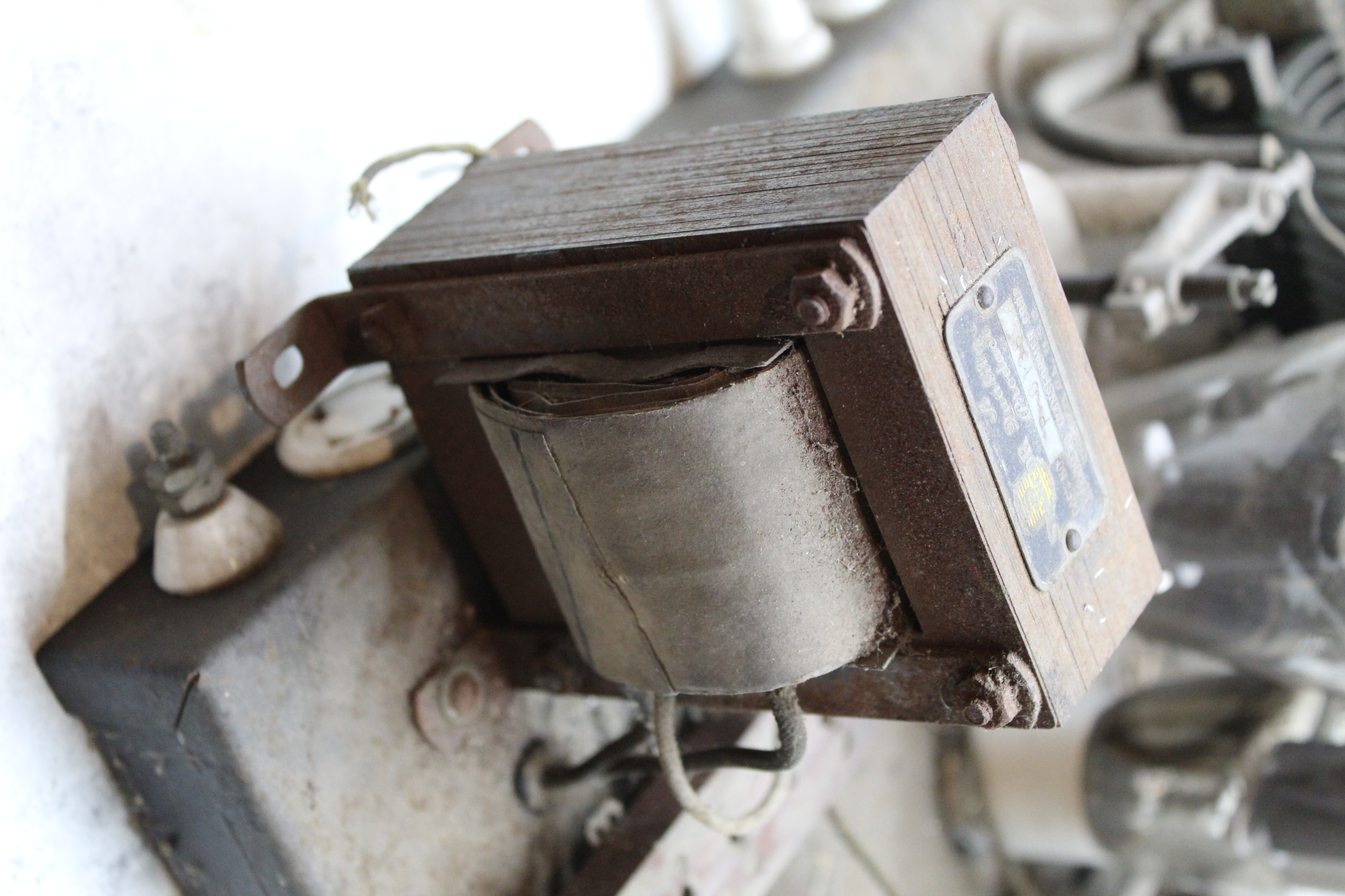
There is the aforementioned lack of HV connector from the power supply. And the HV connector wire under chassis runs through an apparent rear panel "Aux" plug before it goes up to the plate current meter and on to the plate coil. I'm guessing the Aux plug is for connecting the high power modulator from UAT Kit #5? But even more puzzling to me is the outboarded filament transformer squeezed on to the back of the chassis behind the grid coil connector. Reading the 1930's literature, there was nothing wrong with placing the transformer on the RF chassis. But what was the kid thinking of when they squeezed it on there? The UAT-4 was part of Utahs' "build-a-unit" suite of do-it-yourself kits. So maybe when they laid out the RF deck they measured wrong and had to squeeze it on the back side? But even rearranging the parts in any other configuration, I don't see any place that the transformer would fit. There are no other unused chassis holes where a smaller original transformer would have been placed and maybe this one was a too-big replacement for the original. So there's a mystery to add to my general confusion about how this amplifier works. Because it mates with the UAT-1 Exciter which can cover 160 to 10 meters (theoretically) I have to assume that this amplifier does the same. And that makes sense with the plug-in grid coils. But how does the fixed plate tank also tune all the bands? The plate coil taps are tied to the antenna output leads. I would expect taps to be available for tuning the plate circuit for the different bands. There are none. The 425pF tuning condnser is very large. Most period amplifiers are using 100pF. The grid dip meter shows resonance for 80 and 40 meters using the full travel of the condenser. How are the other bands tuned? Guess I'll be doing a lot more reading before I do anymore digging into this thing. |
|
|
A Little Progress, Maybe |
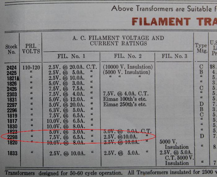
Perhaps the outboarded transformer mystery is solved. Probably there was only one original filament transformer that had dual windings for 2.5 and 7.5 volts and was on the power supply chassis. As a matter of fact Utah manufactured that very transformer, No. 2298 listed in a late 1930's Utah catalog. |
 |
|
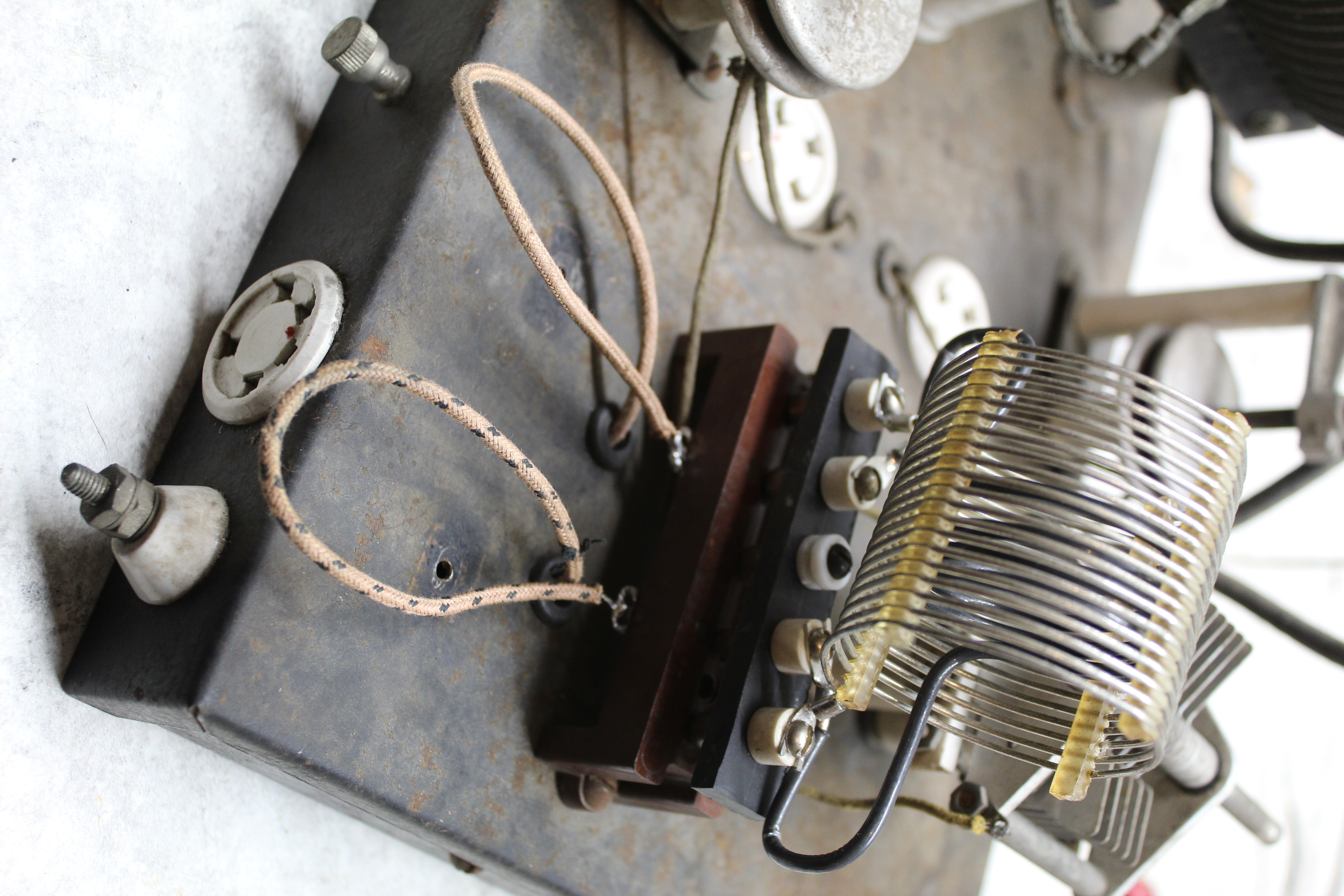
Around the Stancor transformer on the power supply chassis are 4 empty holes where the original Utah transformer was probably mounted. So the kid blows up both filament windings on the Utah transformer (and maybe takes out the grid meter wire too?). Then gets 2 separate transformers, mounts the 2.5V on the power supply chassis for the 866's and then shoehorns the 7.5V transformer on the RF deck for the T-55's. All well and good. Except they also removed the input wires to the grid coil coming from under chassis, and used those 2 holes to run the transformer leads. So the only way this thing was amplifying anything was with clip leads from the UAT-1 output to the grid coil connector tabs. |
 Transformer wires in the holes - Empty grid input tabs |
|
Ok, whatever. The transformer has to go or this thing is never going to come back to life. It is not likely that a dual 2.5V/7.5V filament transformer is going to show up anywhere anytime soon. So maybe we can try and shoehorn it back onto the power supply chassis? Remove the unused but historically correct Aerovox capacitors? Some kind of bracket to mount both transformers horizontally and stack them on top of each other? There's only 6-1/4" of vertical space to do it. It will be very, very tight. |

|
|
Rearranging The Power Supply |
There wasn't enough room to stack the 2 transformers so I wound up pulling the Aerovox filter capacitor in the middle of the chassis and replacing it with the transformer.. |
 |
|
Underneath I ran the secondary filament wires to the 5-pin connector. On the RF Deck underneath I ran new grid input wires from the standoffs through the now open chassis holes to the grid coil connector pins up top. |


|
 |
|
It is apparently not easy to find 5-pin, 2-1/2" wide plug-in connectors with 5/8" pin spacing for the grid coil. So I obtained a lot of coils and coil parts, took a piece of bakelite, cut it down to size and drilled some holes in it. I fashioned together this grid coil with the pieces and parts, a chunk of old AirDux and some stiff #14 insulated wire inside for the link coil. The Millen grid dip meter says it's resonant in and around the 40 meter band. We'll see. |
|
With everything put back together I connected the 5-pin plug, hit the power button and both T-55's lit up nice and bright. So far so good. But I can't avoid playing around with the high voltage anymore. Time to move on. |
 |
|
Some Output |
|
I'm still a little squeamish with the 1500 volts, and I've really got to keep my head on straight with the lashup I've got going on the bench here. But I think I'm making some progress. I put the plate transformer on a separate Variac so I could start testing at some reasonably sane (for me) voltages. It's also not clear to me how the amplifier with its 5K grid leak resistor was keyed. So I built up a fixed bias supply for it and I hooked up the keyed UAT-1 for input. With 400 volts on the plate, I was able to squeeze out some RF from a 40 meter crystal in the UAT-1. Tuning up was very touchy and unstable, but once I got it set, on keydown the Waters wattmeter said 3 watts, tinySA had a nice sharp peak at 7050 kHz, and the NRD-535D had a nice clean tone coming out of the speaker. Increasing the plate voltage towards 500 volts suddenly sent the plate tank into oscillation as I let up on the key. |
 |
|
I randomly twirled the two neutralizing capacitors and tried again. This time I was able to bring the plate all the way up to 800V without any oscillations and an output of almost 25 watts. Studying the final tank coil I noticed that the antenna taps were not symmetrically located. One was attached to the grounded center ring, and the other offset one ring away. Perhaps the neutralizing problem? I moved the center ring tap over one ring and tightened it down and broke out the oscilloscope. I was able to see well defined nulls on each side as I adjusted the capacitors. Once more I nervously brought up the plate voltage this time to an increasingly loud transformer\chassis humming 850 volts and was able to measure 50 watts on the Waters power meter. We are definitely making some progress. My homebrew grid coil seemed to be working on 40 meters but I had been perusing eBay looking for a variety of coils that would fit in the UAT-4 grid coil socket to use on the other bands. I found one (handily labeled on an ancient piece of masking tape "80-40 Meters"). It came with shorting clips on either end of the coil and playing around with it found that it would indeed work on 80 and 40 meters. I threw 80 meter crystals and coils into the UAT-1 and tossing fate to the wind with the new grid coil I cranked up the amplifier plate voltage to 1000 volts. I read 70 watts output on the Waters. I reconfigured for 40 meters and again at 1000 plate volts, 90 watts out on 40 meters. I tested fate and inched the plate voltage higher, but at 1100 volts it broke into oscillation. OK, but I now had two bands working (mostly) and almost 100 watts out on each one. Figuring I was on the right path I tore down my bench test lash-up and reinstalled the power supply and RF Deck back in the metal cabinet. |
|
Metal Cabinet Oscillations |
|
Back with the UAT-1 setup for 40 meters I started to recreate the UAT-4 outputs and was surprised to find that I was now getting plate tank oscillation as I increased the plate voltage below 1000 volts. The neutralization capacitors require a vertical tweaker to make the adjustment so I pulled the RF Deck out, double checked the capacitor settings (which were still good), reinstalled the deck and once again plate current took off. Figuring that the metal cabinet was messing with the neutralization capacitance I was able to spin the outside capacitor to adjust for the null but there was no way I was going to be able to get in to the other one towards the front of the cabinet. |
 |
|
I drilled a small hole in the top of the cabinet right over the front capacitor, just wide enough for a plastic tweaker to fit down into the capacitor slot. I had to navigate past the grid meter which was sticking out close to the vertical path but I got the tweaker in and readjusted the neutralization. Firing up again, plate current took off at around 700 plate volts. I pulled the RF Deck back out and stared at it. The new grid coil seemed to work OK. But it was a long coil, one end within a 1/4 inch from the side of the cabinet. The other end bumped up against the glass of the rear T-55 causing it to sit slightly askew in the tube socket. Was there some feedback happening here? I put the RF Deck back on the top shelf but let the chassis back end hang out from the shelf. I fired it up and at 900 plate volts I was measuring a good 90 watts out. No feedback, no oscillations. I moved the shelf all the way into the cabinet. Plate current went into oscillation. It turned out that as long as the rear end of the chassis was sticking out at least 1-1/2 inches, it was fine, no oscillating. |
 |
|
One final try had me reroute the grid input wires under the chassis away from the HV line but it made no difference. I was stuck. I don't have an EE degree and not much experience with amplifiers. To say nothing of an amplifier with 87 year old technology. I'm just a technician. With no manual and no schematic for guidance I didn't know where to go. I pushed the UAT-4 against the wall and moved on to other projects. |
|
Starting Over With An Original UAT-4 Schematic |
|
Last November at the AWA Annual Conference in Rochester, N.Y. I had talked with Joe W3GMS. Not only was he the proud owner of 2 UAT-1's but he had copies of the complete original manual. He knew he had them but they were buried somewhere in a filing cabinet and he promised to send me copies when he found them. I came home and struggled through the winter with the amplifier and then put it aside in frustration. As spring arrived I made my first ever trip to the Kutztown Antique Radio Fair in May. Even though I had been avoiding the UAT-4 for a few months the obsession was still there. I was hoping to find anything with a Utah Radio Products label on it. Alas nothing of the sort was to be found and I only came home with a junker National NC-100A. But what a surprise on returning home to open the mail and find copies of UAT-1 Manual. Joe had come through. |
 |
|
Quickly looking over the manual I was astounded to find that the back page included a schematic not only of the UAT-1 Exciter but also all of the other UAT boxes, plus an unknown to me Remote Control box. All 6 schematics were crowded onto a ripped and stained piece of paper. But it was mostly readable. Like I said before, I'm a technican. We live and die by the manual and the schematic. Now that I had one I was ready to dive back into the UAT-4. |
 |
|
With the oscillation problem arising from the metal cabinet I had been toying with the idea of building a wooden cabinet for the amplifier. I started on one and used it to to begin testing again. I setup the UAT-1 for 40 meters and again found that there was good amplifier output until I reached around 1100 plate volts when it broke into oscillation. At least I was recreating the original problem 6 months later. Studying the schematic there were two things that jumped out at me. First was the grid bias. There was no provision made for fixed bias, the grid resistor was supposed to be 2.5K/20 watt instead of the 5K that was installed, and the grid meter was installed on the wrong side of the resistor. Second was the HV bleeder resistor which was supposed to be 50K/50 watts instead of the 34K/150 watt monster I had shoehorned onto the power supply chassis. I decided to go back to the original design and skip the external bias supply. If Oliver Read W9ETI designed it to work with a simple grid resistor then it should still work that way 87 years later. I rearranged the grid meter but left the 5K intact. Too many changing variables at once might complicate figuring out what the problem is. With the grid meter repositioned I setup the UAT-1 for 40 meters and this time closed the key for constant drive. The UAT-4 grid meter was showing 50mA drive as I slowly brought the HV up. At 1000 volts I was already at 90 watts output. I passed 1100 volts with no oscillations. All the way to 1400V, max plate voltage according to the schematic. Plate current stood at 180mA and the Waters was reading 170 watts output. The chassis and transformer were buzzing like hell but I had a stable, clean, output. I reset the UAT-1 for 80 meters and again went for full plate voltage. 1400 volts, 125 mA and 130 watts output. This thing works. |
 |
|
I decided to leave the 5K grid resistor as is and concentrate on the bleeder resistor. I had a hunch this would have more effect on the power output. The 150 watt variable I was using had a broken wire on the far end so I had to tap down to find continuity and all I could get was 34K. I guessed that maybe this was drawing the HV down a bit. After a few weeks of searching I gave up trying to find a nice fat, brown, ceramic, 50K wirewound and went for this modern, brushed metal, tiny, apparently heat-sinked Chinese resistor. Some Chinese components I have purchased trend towards the lower end of manufacturing quality. We'll see about this one. I bought 4 in case I need spares. Hope it doesn't require heat compound to bind to the rusty chassis top.
|
| With the new 50K bleeder resistor the UAT-4 is working at 75% efficiency | |||
| Band | Plate V | Plate I | Power Out |
| 40 Meters | 1400 V | 230 mA | 240 Watts |
| 80 Meters | 1400 V | 120 mA | 130 Watts |
|
I still can't get used to the vibrations and humming as the UAT-4 sits there at 1400 volts but it is producing power output that I never really believed it could do. Following the schematic I moved the T-55 7.5 volt filament center tap from ground to the Key Jack on the back of the power supply chassis. It also calls for a 400 ohm resistor in the 7.5 filament center tap line, and the 2.5K grid resistor. I'm not sure if I should add these changes or try and put the rig back in the metal cabinet. I'm thinking it was probably the external bias supply that was causing the feedback oscillations? I can't believe just moving the grid meter to the ground side of the grid resistor was the fix? |
 |
|
A Wooden Cabinet |
|
I finally gave up on the original metal cabinet. With the new configuration pumping out 240 watts with the chassis on a wooden shelf I put it back inside the metal cabinet and it immediately went into oscillation. Even with the back end of the RF deck hanging out the back of the cabinet. So I put the metal cabinet aside and I finished construction of this: |
 |
|
It's all 3/4" pine board. Because that's all I have. So it's 1-1/2 inches wider and taller than it needs to be. The front panel is plexiglass and the whole thing spray painted black. The labels are just printed paper from photoscans of the metal cabinet. Rubber cemented to the black painted plexiglass and given a quick spray of clear acrylic. I think if you stand across the room, dim the lights and squint at it, it doesn't look half bad. |
 2023 WA2FXM - Mark Mohrmann 2023 WA2FXM - Mark Mohrmann |
 |