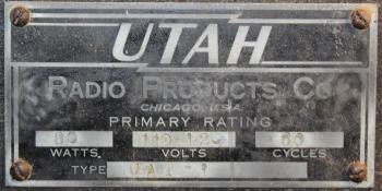
| A Utah Radio UAT-1 |
|---|
|
| The Rebuild | |
|---|---|
|
Opening It Up 

|
|
|
The insides were a bit rusty and crusty but overall not too bad. I pulled both chassis out of the cabinet, started sweeping out the dirt and crud. With a little metal scraping and scrubbing followed by a light coat of black spray paint both the power supply and RF chassis' looked serviceable. |

|
|
Someone's been in here before. Francis Emrich W2VDI of Scotia, N.Y. was active back in the late 1950's. He put his mark on this UAT-1. And had his 5Z3 rectifier tubes tested at Humpel's Radio Service in Amsterdam. |


|
|
The Power Supply |

 Before After |
|
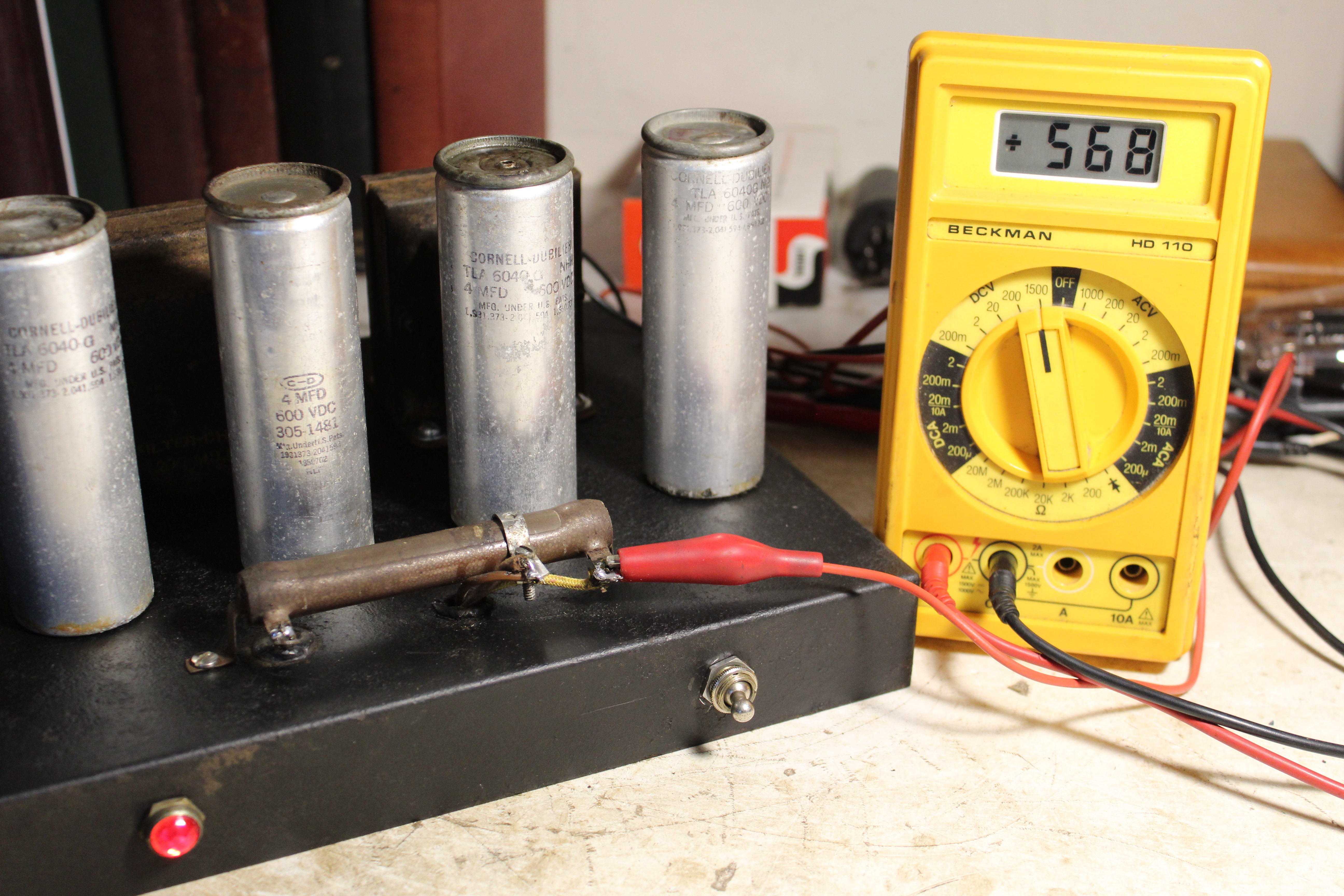
Electronically the power supply was in good shape. The transformer, both chokes and all 4 filter capacitors all checked out ok. Underneath the only problem appeared to be the 25 ohm power resistor was open. A junk box replacement was an easy fix. Other than a new power cord there wasn't much else to do but clean the switches and see how it would respond. Up on top the dropping resistor needed a little attention. The clamp had created a dead spot on the winding where it had been sitting all those decades. I had to shift it over a hair to get good contact again. |
|
I plugged it in to the Variac and brought it up to 117VAC. The red power lamp glowed and it was putting out a hefty 568VDC. A very good start. |
|
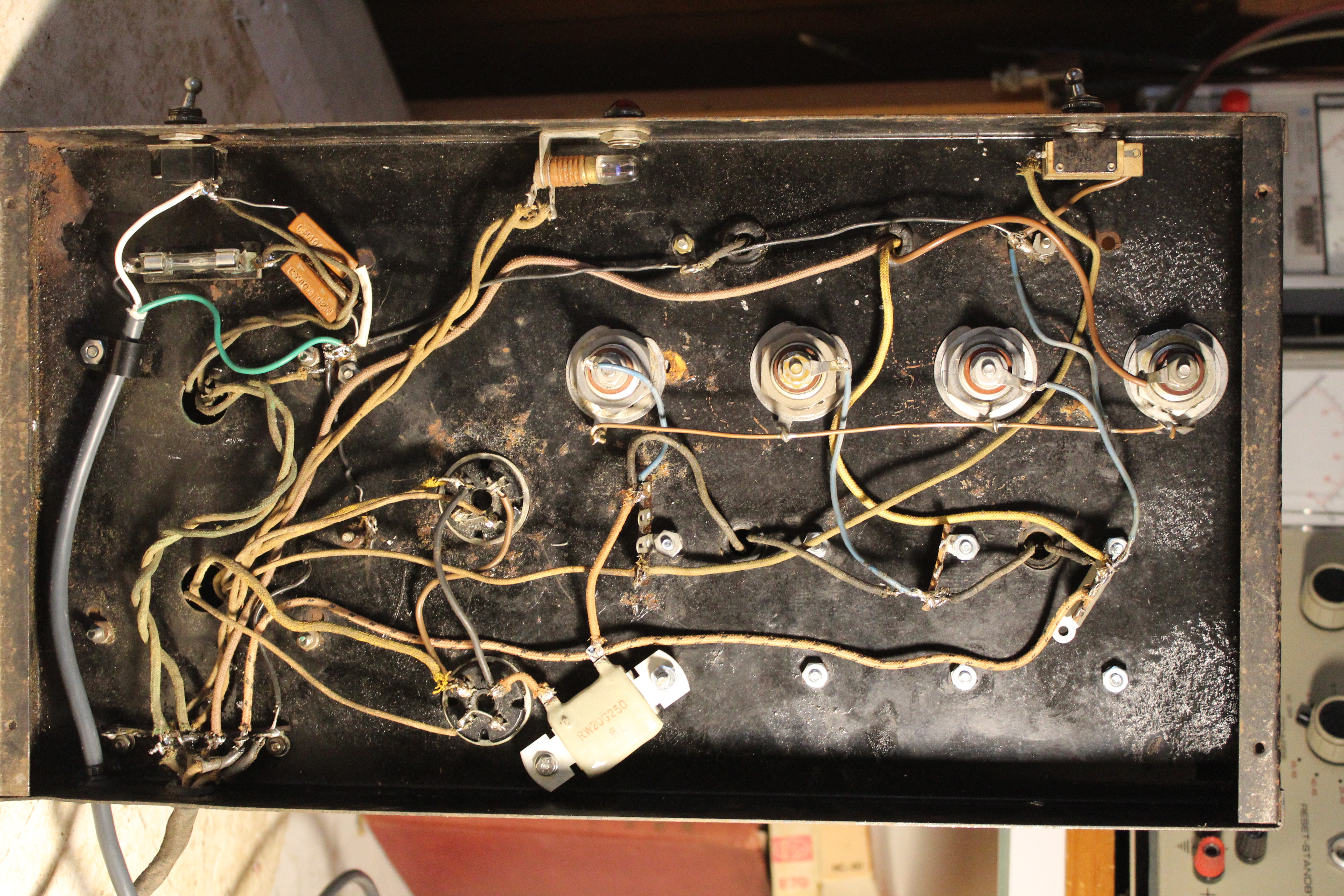
The RF Deck |

 |
|
The RF Deck wasn't in bad shape either. A 15K power resistor was another easy replacement. One of the ceramic variable condenser insulators was cracked. Used a little JB Weld on it, just enough to keep it together. When everything was put back together it was time to fire it up and see what happens. The rig came with 3 homemade coils for 40 meters, so I dug out my 7050kHz crystal from the Viking II sitting on the shelf. I cracked open a dead Sylvania 227 tube and fashioned a proper 5 pin crystal holder for the UAT-1 crystal socket. Going into my 50 ohm transmission chain to the dummy load I was able to get about 30 watts out with 360 plate volts and 150 plate milliamps. First thing I noticed was that the UAT-1 doesn't key the oscillator. It has a Send/Rcv switch that cuts the B+ when you want to receive. Which means first throwing your T/R switch, then throwing the Send/Rcv switch, then wait 3 seconds listening in your receiver as the signal dies down with the dissipating B+, then go ahead with your QSO. Not ideal. I was pretty sure the fix had something to do with moving the cathode of the oscillator over to the key line. But this being my first foray into a pre-WWII transmitter I wasn't quite sure. So I pretended I was a kid in the 1930's who wasn't sure what to do and just started reading the ARRL manuals from 1937 through 1940. Sure enough, take the cathode off of ground and move it over to the key. Voila. It worked. I buttoned everything back up, fired it up on the 40 meter vertical and with the smell of 85 year old transformer heat filling up the shack I worked a KG3 down in southwest Pennsylvania. |

|
|
From Rock Bound To A VFO I've known all along that I was going to have to eventually do something about a VFO. The FT-243 looks very cool sitting in it's little cup there but if I'm seriously going to use the UAT-1 I've got to come up with some variable tuning. Researching the idea of variable tuning I found that the early 1940's is when the VFO started to be a thing. Henry Rice W9YZH described his design for a simple Electron Coupled Oscillator (ECO) exciter and its power supply in the January 1941 issue of QST. Two months later James Millen announced his first attempt at a commercial unit, The Rice-Variarm. |
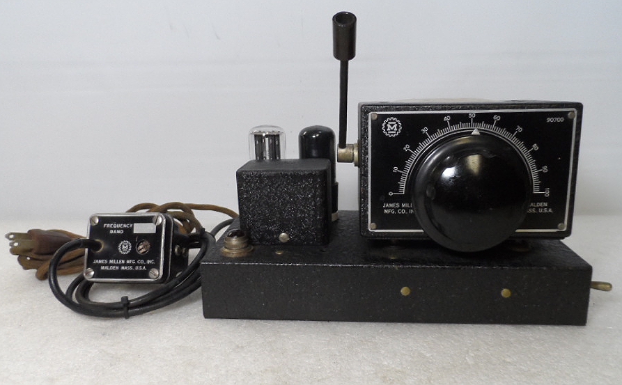 A James Millen 90700 Variarm Electron Coupled Oscillator |
|
Ever since I saw this picture of the Variarm I have coveted one immensely. But alas, it would seem there aren't many of them around. I'm keeping my eye out for one to show up somewhere, but in the meantime I dusted off the Johnson VFO 122 and started seeing if I could make it play nice with the Utah. First things first, I busted open another dead 227 and soldered a UHF connector to it to accept the Johnson coax connector. |

 |
|
Next I disabled the oscillator test lamp and ran a keying line wire out through the lamp wire hole. Somehow I had to get the key signal to the Johnson. I opened the Johnson up and messed around with it for awhile and with alligator clips to the key line and more alligator clips to the Heathkit Power Supply I was able to power up the Johnson and got a warbly keyed signal out of it, through the Utah. Once I buttoned the Johnson back up it was rock solid. |
 The VFO 122 hooked up to the UAT-1 |
|
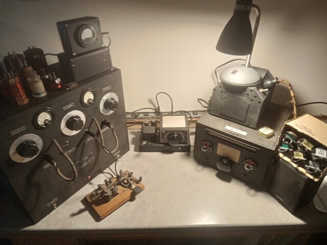
With the Johnson VFO hooked in with alligator clips, and a refurbished Hallicrafter S20-R receiver I was able to work the 2022 Linc Cundall QSO party in January. I ran up 9 states including a proper 1939 QSO with Jim W8KGI down in Scandia, N.M. with his National NTX-30 and array of pre-WWII receivers. But Sunday afternoon a few hours before the end, in between QSO's I suddenly lost the high voltage in the Utah. With accompanying slightly burning smell wafting through the shack. Oh well. I've got a whole year before the next LC to get it straightened out. |
 All setup for the Linc Cundall QSO Party |
|
Newer Isn't Always Better When I first dug into the UAT-1 power supply the only real problem was the bad power resistor that was easily replaced. All the main power supply components were still good. I know that those old oil-filled fiter capacitors are generally ok and all 4 of them measured on or around 4uF. But just in case they were starting to get tired I disconnected them all and replaced them with brand new Miec 4uF 600V electrolytic cans. |
 |
|
Imagine my surprise this morning when I started disconnecting wires to hunt down the shorted B+ and found that it was one of the brand new capacitors that had failed. I pulled it out, rewired the old Cornell-Dubilier TLA6040G back in and voila!, B+ back at +500VDC. It seemed like a no-brainer at the time. I had the capacitors, it was an easily accessable fix, why not? Because I need to listen more to my inner tech self. If it's not broke, don't fix it. |
 All better |
|
I Found One |

|
|
It showed up, magically, one day on eBay. It appears to be all original. Even the kludged, two-prong output coupler attached with ancient cellophane tape. I dusted it off and opened it up. Just 5 paper capacitors to replace. |

 |
|
Of course, the real problem with most Variarms is the 165 ohm dropping resistance in the filament chain. Millen used a resistance wire in the power cord. Mine was opened up so I needed to figure out a replacement scheme. I did some research and it seemed like there were three ways to deal with it. The most elegant one to me was replacing the 3 tubes with higher filament voltage versions. All I needed to find was a 12K7 for the oscillator, a 50L6 for the amp and a 50Z6 for the power supply. 12+50+50 = 112, close enough to avoid a huge filament dropping resistor. |
 Consulting my inherited trove of tubes |
|
I pored through my inherited 20 boxes of tubes. I was able to come up with a 50L6 and a 25Z6, but that was it. So, idea #2 is to replace the resistance wire with a 165 ohm power resistor. I put two 320 ohm 10 watt resistors in an old beat up plastic box with an ac cord and a pigtail to mimic the original power cord going to the Variarm inards. I brought it up slowly on the Variac and was pleasantly surprised when the voltage across the 25Z6 hit 25 volts just as the Variac hit 117 volts. I turned on the NRD-535D receiver and heard a nice clean signal as I VARIed the ARM up and down. It worked. |
 |
|
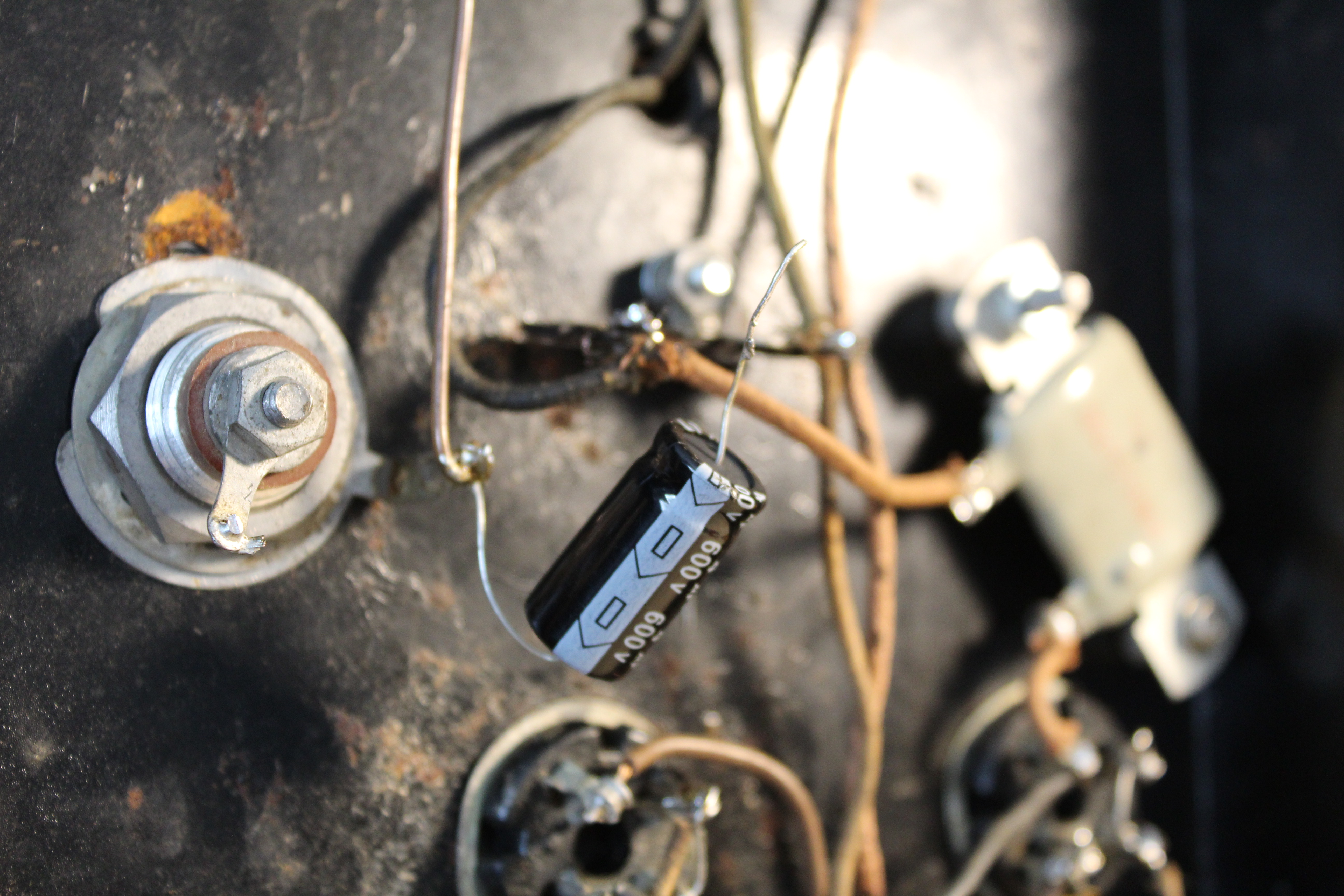
But jeesum, did those new Dale resistors get hot. A faint puff of smoke wafted up to the desklamp as the resistors burned off something from the recent manufacturing process. That heat would never do inside the Variarm chassis and I didn't need another box cluttering up the operating desk. So I went with the 3rd solution, a capacitive dropper. |
 |
|
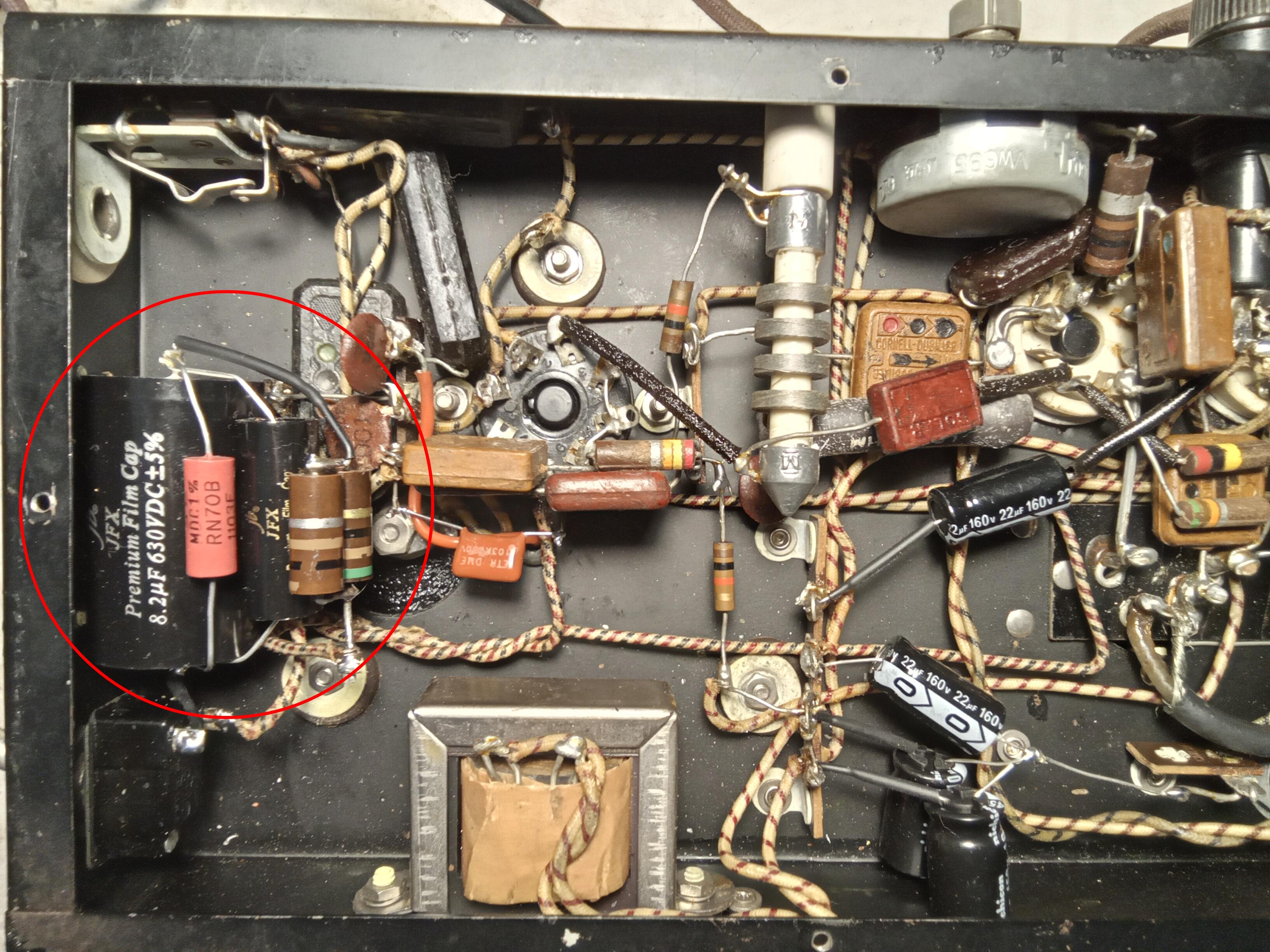
I had heard of the capacitive dropping scheme but wasn't really familiar with it. I went to the UK Vintage Radio website and read about it. They even have an Excel spreadsheet calculator to come up with working values. I plugged in some numbers and came up with a 9uF capacitor with a 30 ohm, 3 watt surge limiter resistor. I had to search around a bit for 9uF capacitors that would fit under the chassis and wound up with an 8.2uF and 0.82uF in parallel. I put a 110k bleeder resistor across it and from the junque box fashioned about 30 ohms from two carbon 2 watt resistors. On first power up I was getting no B+ at all, but after studying the situation I realized I put the dropping network in the wrong leg of the AC line. The Variarm needs to drop the heater chain voltage, but it also needs the 117AC return for the B+. I swapped wires around, brought it up on the Variac and again got a good 25 volts across the tubes at about 117VAC input. |
|
Next was repairing the misused coupling box. The inner conductor of the coax output cable had broken off because whatever cable strain relief had been in there had disintegrated and the cable was just flopping around in the hole. I got a small piece of solder braid and soldered it to the center conductor to give it a little bit of leeway. A couple wraps of electrical tape was all I could do for strain relief but it should be ok with a little TLC. |

 |
|
Finally, the output coupler had a kludged 2-pin crystal plug. Held together with ancient cellophane tape. I added some modern electrical tape when I was testing it out, but then I fashioned a proper plug. I salvaged a 5-pin tube base, trimmed it down to size, bolted an old capacitor aluminum band to it and added some mounting tabs. It plugs into the UAT-1 crystal socket very nicely. |

 |
|
And it was good enough to work 8 stations during the AWA 2023 Linc Cundall Memorial QSO. |
 |
 2022 WA2FXM - Mark Mohrmann 2022 WA2FXM - Mark Mohrmann |
 |